Typical coil performance, H934 relay contact ratings, Current monit oring – Veris Industries H720 Datasheet User Manual
Page 2: Application/wiring diagram (h904), Dimensional drawings ordering information, Accessories, Example linear output (h720)
current monit
oring
800.354.8556
+1 503.598.4564
www.veris.com
MODEL AMPERAGE RANGE
STATUS OUTPUT
MIN. TRIP
POINT
RELAY
TYPE
HOUSING STATUS
LED
RELAY
POWER LED
UL
H720
lower limit: 0A
Upper limit: 20 to 200A
4-20mA
n/a
none
Solid-core
n
H904
3.5 - 135A, 20 - 75 Hz
Max. N.O. 0.1A@30VAC/DC
3.5A or less
none
Split-core
n
n
H934
SPST, N.O.
n
n
n
NOTE: The H904 is not intended for use in staged pump or variable inlet vane applications.
H904/934
Voltage
AC DC
24V................................... 10mA
10mA
TYPICAL COIL PERFORMANCE
Resistive..................................5A@250VAC, 30VDC
H934 RELAY CONTACT RATINGS
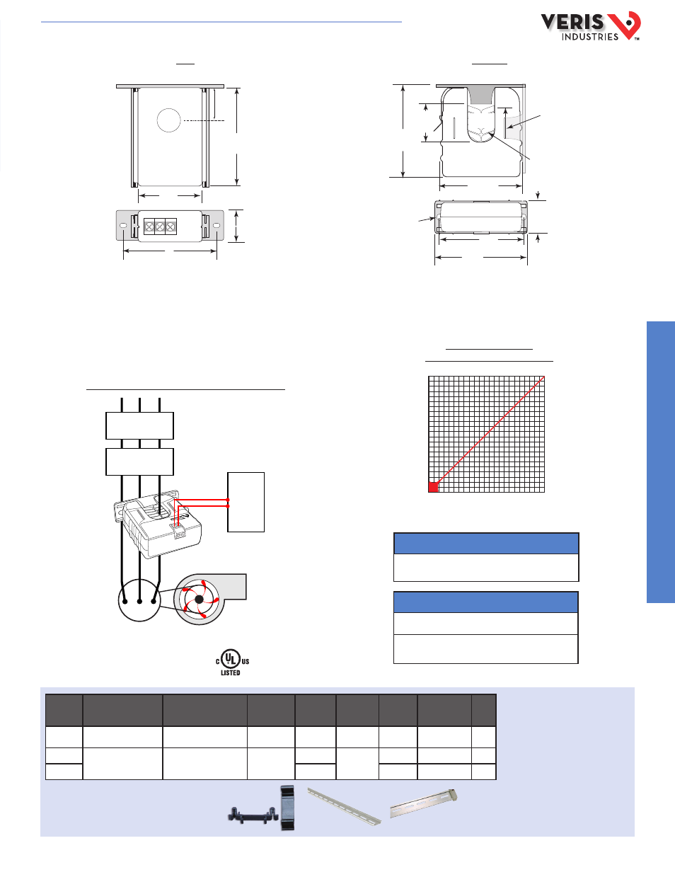
APPLICATION/WIRING DIAGRAM (H904)
Monitoring Fan /Pump Motors for Positive Proof of Flow
DIMENSIONAL DRAWINGS
ORDERING INFORMATION
H720
EXAMPLE LINEAR OUTPUT (H720)
Scale software as shown
Requires 12-30VDC for sensor power
SENSED AMPS
200A
4mA
0A
20mA
SENSOR OUTPUT
* Terminal block may extend up to 1/8” over the height dimensions shown.
Removable Mounting Bracket
Self-gripping Iris
1.0”
(25 mm)
0.8”
(21 mm)
1.1”
(26 mm)
**3.1”
(79 mm)
2.8”
(70 mm)
Ø 0.3”
(8 mm)
1.4”*
(36 mm)
2.5”
(64 mm)
3.0”
(76 mm)
Bracket can
be mounted
on three sides
for added
installation
flexibility.
Fan or Pump
CONTROL
DI
Motor
VFD
CONTACTOR
ACCESSORIES
DIN Rail Clip Set (AH01)
DIN Rail (AV01) and DIN Stop Clip (AV02)
AH01
AV01
AV02
3.13"
(80 mm)
0.33"
(9 mm)
2.15"
(55 mm)
3.0"
(76 mm)
1.00"
(26 mm)
0 0.7"
(19 mm)
Removable/Adjustable Mounting Bracket
E150462
HQ0001758.B 01131