Caution, Installation guide, Operation – Veris Industries H822-20 Install User Manual
Page 2: Calibration
6%2)3
INSTALLATION GUIDE
H822-20
Z202375-0B
PAGE 2
©2008 Veris Industries USA 800.354.8556 or 503.598.4564 / [email protected]
10082
Alta Labs, Enercept, Enspector, Hawkeye, Trustat, Veris, and the Veris ‘V’ logo are trademarks or registered trademarks of Veris Industries, L.L.C. in the USA and/or other countries.
opEration
The H822-20 is a current transducer that senses current (amperage) in the 0-20A
range. This represents the maximum current that can be applied to the monitored
conductor. The H822-20 transforms the monitored current into a 0-5VDC output
suitable for connection to building controllers, or other appropriate data acquisition
equipment. The H822-20 requires no external power supply to generate its output.
notEs
troublEshooting
For load currents less than sensor minimum rating:
Wrap the monitored conductor through the center hole and around the sensor body
to produce multiple turns through the "window." This increases the current measured
by the transducer.
0.5A
4x
DANGER: 5A CTs can present hazardous voltages.
Install CTs in accordance with manufacturer's instructions.
Terminate the CT secondary before applying current.
H681x-5A CT
150A
300A:
5A
2.5A
> 20A (H822-20 max.)
For load currents greater than sensor maximum rating:
Use a 5 Amp (H681x series) Current Transformer (CT) as shown.
Problem
Solution
No Reading at Controller
• Check for control voltage at sensor (<20V).
• Check for amperage in monitored conductor (> 2A).
• Assure that sensor core mating surfaces are clean.
CAUTION
RISK OF EQUIPMENT DAMAGE
t %FSBUFUIFQSPEVDUTNBYJNVNDVSSFOUGPSUIFOVNCFSPGUVSOT
UISPVHIUIFTFOTJOHXJOEPXVTJOHUIFGPMMPXJOHGPSNVMB
3BUFE.BY"NQT/VNCFSPG5VSOT.BYNPOJUPSFE"NQT
FH"5VSOT"NQTNBYJONPOJUPSFEDPOEVDUPS
t 'BJMVSFUPGPMMPXUIFTFJOTUSVDUJPOTDBOSFTVMUJOPWFSIFBUJOH
BOEQFSNBOFOUFRVJQNFOUEBNBHF
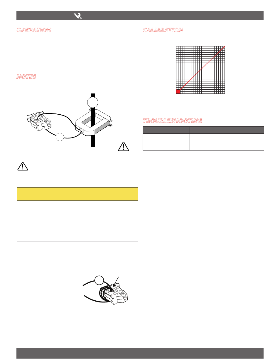
calibration
Scale the controller software to match the current transducer’s output (0-5VDC).
SENSED AMPS
20A
0 VDC
0A
5 VDC
SENSOR OUTPUT
<2A (sensor min.)
Controller must be programmed to account
for the extra turns. e.g., if four turns pass
through the sensor (as shown) the normal
controller reading must be divided by 4.