Pressure, Ordering information accessories, Current/voltage control tri-state control – Veris Industries EP3 Datasheet User Manual
Page 2: Side view front view dust cover
pressure
800.354.8556
+1 503.598.4564
www.veris.com
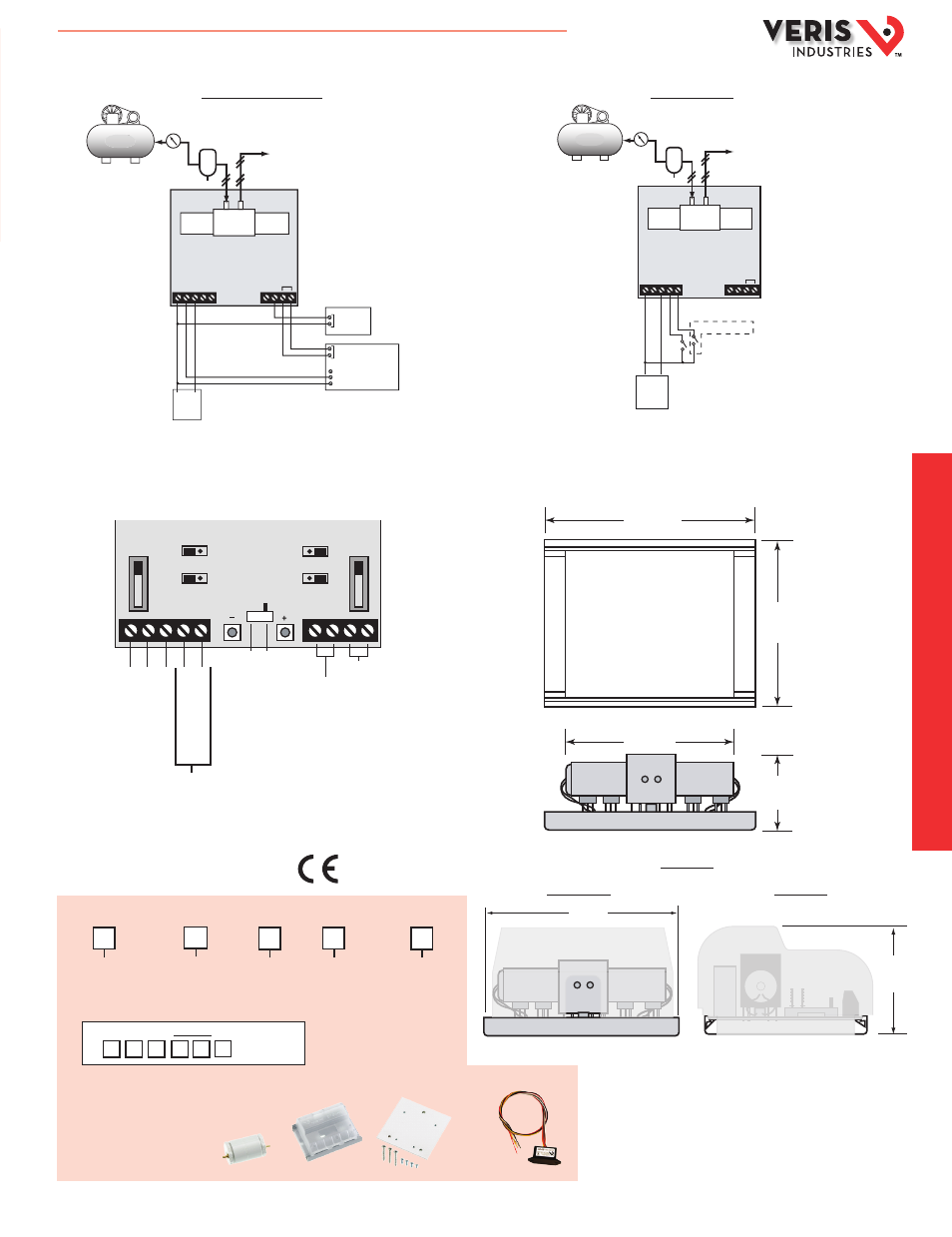
APPLICATION/WIRING DIAGRAMS
DIMENSIONAL DRAWINGS
CONFIGURATION
• Input switch set to voltage (0-5VDC or 0-10VDC)
• Input volt jumper set to either 0-5VDC or 0-10VDC
• Input switch set to 4-20mA
• Output jumper set to 0-10VDC
• Input switch set to "TRI-STATE"
• Tri-State jumper set to "ON"
Current/Voltage Control
Tri-state Control
POWER
SOURCE
+
-
+
-
TRI-STATE CONTACTS
PWM CONTACT
CH1
OR
CH2
OR
Subtrac
t
Pr
essur
e
Add P
ressur
e
AIR COMPRESSOR
GND INPUT +24
V
CH2 CH1/PWM
4-20mA 0-10V
AL
ARM C
ONT
AC
TS
BRANCH
TRAP/
FILTER
20-45psi
Regulator
GND INPUT +24
V
CH2 CH1/PWM
4-20mA 0-10V
ALARM C
ONT
AC
TS
POWER
SOURCE
Digital Input
(Contact Closure)
0-10V PROCESS METER
BRANCH
TRAP/
FILTER
20-45psi
Regulator
+
-
Analog (Out 9-20mA)
Common
AIR COMPRESSOR
+
-
GND
INPUT
24
V
CH2
CH1/PW
OPERATION
MODE
TRISTATE
ALARM
P-LOSS MAN
INPUT VOLTAGE
0-10V 0-5V
TRI-PULL-UP
ON OFF
OUTPUT
4-20mA 0-10V
ALARM
OUTPUT
4-20mA/0-10V
Tristate Timing
Network
FS Point
Zero
RUN
4-20mA
Voltage
Tristate
PWM
Network
Control
SETTING
INPUT
+
-
Subtrac
t
Pr
essur
e
Add P
ressur
e
Aut
o
M
anual
SIDE VIEW
FRONT VIEW
Dust Cover
4.9"
(125 mm)
2.1"
(53 mm)
1.8"
(46 mm)
4.9"
(125 mm)
3.5"
(89 mm)
3.9"
(94 mm)
Available
Output
0 = None
3 = Analog output:
0-10VDC, or
4-20mA, selectable
US or EU
S = Standard
C = CE, includes
cover plate
Feedback
= Pressure Loss
Alarm, or
Manual
Mode Alarm
EP3
Failsafe
0 = None
1 = Vent on
Power Fail
Option
Blank = None
2 = EP Cover Plate
3
Example:
EP 3 3 3 1 S 2
Option = Cover Plate
ORDERING INFORMATION
ACCESSORIES
Steel Bracket (AA23), Dust cover (AA43),
Pneumatic Capacitor (AA45),
Triac Adapter (AA49)
AA23
AA43
AA45
AA49
HQ0001829.B 01131