Installation guide, Typical coil performance contact ratings, Wiring color codes contact and coil specifications – Veris Industries V320 Install User Manual
Page 2: Wiring example, V320
Z203397-0B
PAGE 2
©2012 Veris Industries USA 800.354.8556 or +1.503.598.4564 / [email protected]
05121
Alta Labs, Enercept, Enspector, Hawkeye, Trustat, Veris, and the Veris ‘V’ logo are trademarks or registered trademarks of Veris Industries, L.L.C. in the USA and/or other countries.
TM
V320
INSTALLATION GUIDE
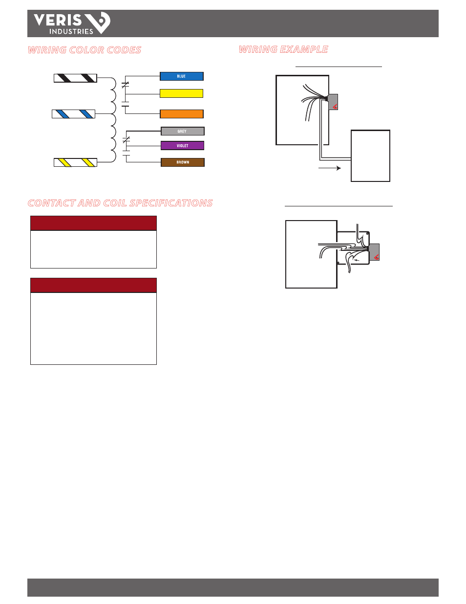
WIRING COLOR CODES
CONTACT AND COIL SPECIFICATIONS
N.C.
Common
24VAC/DC
120VAC
HI
wht/black
LOW
wht/blue
COMM
wht/yellow
Common
N.O.
CONTACT OUTPUT
CONTROL SYSTEM INPUT
White
YELLOW
White
White
ORANGE
blac
k
blac
k
blue
blue
yello
w
yello
w
blac
k
N.C.
Common
N.O.
Voltage
Coil Current
AC DC
24V.......................................... 150mA
64mA
120V........................................ 84mA
-
TYPICAL
COIL PERFORMANCE
CONTACT RATINGS
Resistive............................ 20A@277VAC, 28VDC
Motor................................. 120VAC, 1HP
277VAC, 2HP
Pilot Duty.......................... A300
Ballast............................... 20A@277VAC N.O.
10A@277VAC N.C.
Tungsten........................... 10A@120VAC N.O.
2A@120VAC N.C.
WIRING EXAMPLE
Nipple mount directly to a panel
Nipple mount to a 2x or 4x electrical box
* Isolate any unused wires, e.g. wire nut.
To Load A
To Controls
CONTROL
PANEL
COIL
To Load B
To Power
COM
N.O.
N.C.
To Load B
To Control
Wire
Nuts
CO
IL
CONTACTS
To Load A
To Power
N.C.
N.O.
COM