Caution, Installation guide, Operation – Veris Industries H904 Install User Manual
Page 2: Setup, normal state detection, Nuisance reduction feature, Troubleshooting, Led blink codes
VERIS INDUSTRIES
™
INSTALLATION GUIDE
H904
Z201179-0J
PAGE 2
©2010 Veris Industries USA 800.354.8556 or +1.503.598.4564 / [email protected]
04102
Alta Labs, Enercept, Enspector, Hawkeye, Trustat, Veris, and the Veris ‘V’ logo are trademarks or registered trademarks of Veris Industries, L.L.C. in the USA and/or other countries.
opEration
The H904 is a current-sensitive switching device designed for use with VFD motors.
It is equipped with an auto calibration feature that allows the device to distinguish
between a reduced amp draw due to normal changes in frequency and an abnormal
drop due to belt loss or other mechanical failures.
A change in amperage in the monitored conductor that crosses the switch (setpoint)
threshold plus the hysteresis value will cause the resistance of the FET status output
to change state, similar to the action of a mechanical switch. The status output is
suitable for connection to building controllers or other appropriate data acquisition
equipment operating at up to 30 volts. The H904 requires no external power supply
to generate its output.
The H904 housing offers unprecedented mounting flexibility. The mounting bracket
can be attached in three different places. Additionally, the bracket is compatible with
the Veris AH01 DIN Rail clip, allowing DIN mounting.
notEs
For load currents less than sensor minimum rating:
Wrap the monitored conductor through the center hole and around the sensor body
to produce multiple turns through the "window." This increases the current measured
by the transducer.
4x
1A
CAUTION
RISK OF EQUIPMENT DAMAGE
• Derate the product’s maximum current for the number of turns
through the sensing window using the following formula.
Rated Max. Amps ÷ Number of Turns = Max. monitored Amps
e.g. : 100A ÷ 4 Turns = 25 Amps max. in monitored conductor
• Failure to follow these instructions can result in overheating
and permanent equipment damage.
< 3.5 A (Sensor Min.)
Controller must be
programmed to account
for the extra turns. e.g.,
if four turns pass through
the sensor (as shown) the
normal controller reading
must be divided by 4.
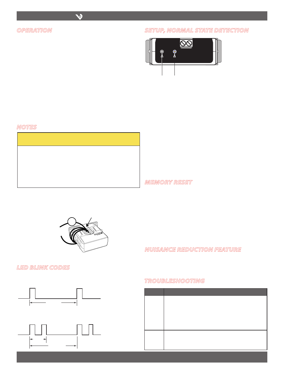
sEtup, normal statE DEtEction
Memory Reset
Button
Status LED
Reset
Output
Status
Establish normal operating conditions (clean filter, normal load)
1.
Start the motor running at 35 Hz.
2.
Push and hold the Memory Reset button for approximately 5 seconds (see
3.
Nuisance Reduction section, below).
Let the drive operate at this speed for 1 minute.
4.
Increase to 42 Hz and run for 1 minute.
5.
Increase to 49 Hz and run for 1 minute.
6.
Increase to 56 Hz and run for 1 minute.
7.
The H904 is now ready to monitor current values and detect
belt loss from 35-75 Hz. Below 35 Hz, it will detect power on/off
states.
mEmory rEsEt
During setup, the H904 automatically determines the setpoint and stores it in
nonvolatile memory at 70% of the measured current. The H904 will require a
Memory Reset if any of the following conditions occur:
The sensor is reinstalled on a different motor.
•
The motor is re-sheaved.
•
The system is air balanced.
•
The motor load changes significantly.
•
To reset the H904, follow the Memory Setup procedure, starting at Step 1.
nuisancE rEDuction FEaturE
The H904 provides a secondary setpoint option of 50% of the originally measured
current. To access this feature, follow the Memory Setup procedure, but in Step 2,
hold the Reset button for 10 seconds instead of 5.
troublEshooting
Problem
Solution
No Reading
at
Controller
• Check for amperage in monitored conductor (>3.5A).
• Check that amperage in the monitored conductor does not exceed sensor
max (135A).
• Check to be sure that no more than 30VAC/DC or 1.0A has passed through
the contact. Voltages or currents above these levels will damage the unit.
• Assure that sensor core mating surfaces are clean and that the core clamp is
completely closed.
False trips
• Use the Nuisance Reduction feature, holding the Reset switch for 10 seconds
instead of 5. This will reset the memory and decrease the setpoint from
70% of memorized current to 50%. In this mode, belt loss must cause an
amperage reduction of 50% or more to be detected.
lED blink coDEs
1 sec
1.25 sec
~0.3
sec
1 pulse per cycle = Normal Operation
2 pulses per cycle = Alarm Status