Po wer/ener g y monit oring, Ordering information, Operation example – Veris Industries H663 SERIES Datasheet User Manual
Page 2: Model number of cts amperage range output
p
o
wer/ener
g
y monit
oring
800.354.8556
+1 503.598.4564
www.veris.com
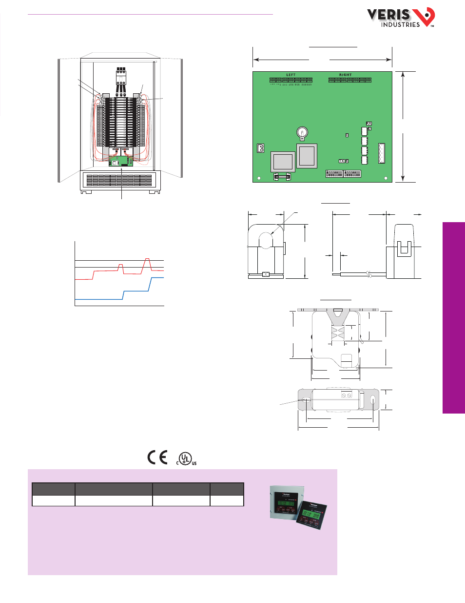
APPLICATION/WIRING EXAMPLES
DIMENSIONAL DRAWING
ACCESSORIES
Network Display (H8936)
ORDERING INFORMATION
HQ0001911.A 01121
LISTED
44XJ
IND:CONT EQ
OPERATION EXAMPLE
Signal Aquisition Board
1.1"
(27 mm)
1.1"
(27 mm)
0.4" Radius
(10 mm)
1.6"
(41 mm)
6"
(152 mm)
0.3"
(6 mm)
H663 CT (50A)
6
4
2
12
10
8
18
16
14
24
22
20
30
28
26
36
34
32
42
40
38
7.25”
(184 mm)
5.75”
(146 mm)
2.5"
(64 mm)
2.0"
(51 mm)
2.1"
(54 mm)
3.5"
(89 mm)
2.9"
(74 mm)
0.4” x 0.2”
(10 mm x 5 mm)
Slot (2x)
1.3"
(33 mm)
0.6"
(16 mm)
0.5"
(13 mm)
2.1"
(54 mm)
1.0"
(26 mm)
H663 CT (100A)
*20A
*Example represents 20 Amp circuit
†Configurable time delay for alarm and warning
0A
TIME
70% (14A)
Alarm Signal†
60% (12A)
Warning Signal†
Amp
Draw
E ect of
Rebalancing
Critical
State
Ckt. 1
Ckt. 2
Panel Board 1
20
20
20
20
20
20
20
20
20
20
20
20
20
20
20
20
20
20
20
20
20
20
20
20
20
20
20
20
20
20
20
20
20
20
20
20
20
20
20
20
LEFT
RIGHT
41
39
37
35
33
31
29
27
25
23
21
19
17
15
13
11
9
7
5
3
1
42
40
38
36
34
32
30
28
26
24
22
20
18
16
14
12
10
8
6
4
2
Channel 4
Channel 2
Channel 3
Channel 41
H663 Data Acquisition Board
Channel 1
"
"
"
"
"
"
"
"
"
"
Channel 42
"
"
"
"
"
"
"
"
"
"
MODEL
NUMBER OF CTs
AMPERAGE RANGE
OUTPUT
H663SM-xx(H)(E) xx = 42, 30, 24, 12, or 1 (selectable)
Up to 50 A* (configurable)
Modbus RTU
†
For 240 VAC supply voltage version, order the H663SM-xxE.
For the 100 A CT version, order the H663SM-xxH.
For the 240 V, 100A version, order the H663SM-xxHE.
For N2 protocol versions, order H662SM-xx.
NOTES:
* Hole size accommodates up to 6 AWG (10mm
2
) THHN insulated conductors.
† Other protocols available; consult factory.