Typical coil performance, Relay contact ratings (n.o.), Current monit oring – Veris Industries H931 Datasheet User Manual
Page 2: Application/wiring diagram, Dimensional drawing ordering information, Accessories
current monit
oring
800.354.8556
+1 503.598.4564
www.veris.com
MODEL AMPERAGE RANGE
SENSOR
OUTPUT
RELAY
TYPE
RELAY COIL RELAY RELAY POWER LED
UL
H931
0 - 30/60/120A
4 - 20mA
SPST, N.O.
24VAC/DC
n
n
n
H951
12VDC nom.
n
n
n
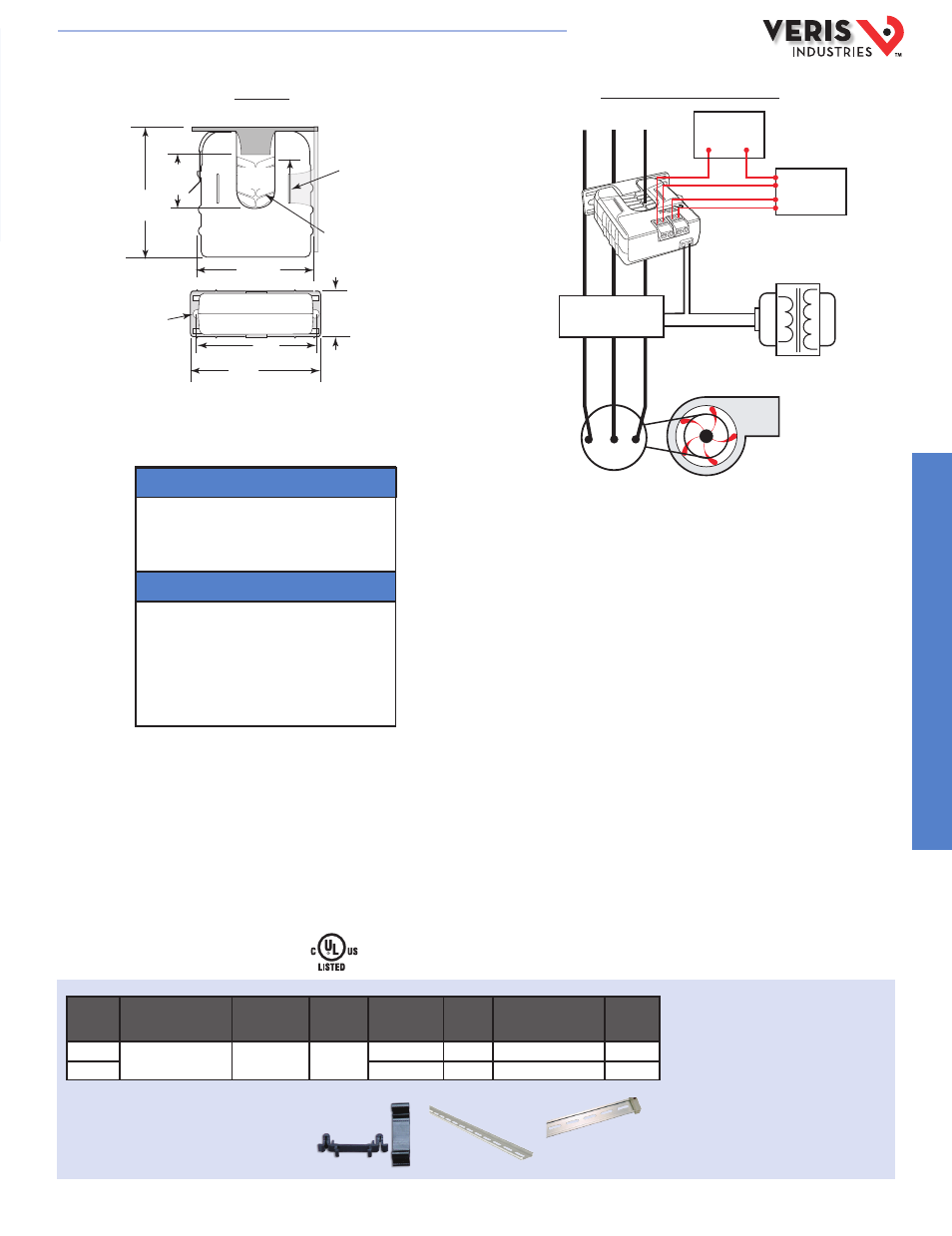
APPLICATION/WIRING DIAGRAM
Trending & Controlling Motor Loads
H931/H951
Voltage
AC
DC
24 ......................................................
....................................................................
15
20
15
12
TYPICAL COIL PERFORMANCE
Resistive........ 5A@240 VAC
5A@30 VDC
Inductive........ 2A@240 VAC
2A@30 VDC
RELAY CONTACT RATINGS (N.O.)
Pull In Voltage (H951 only)
12VDC .............................................................. 8.4VDC
Drop Out Voltage (H951 only)
12VDC .............................................................. 3.0VDC
DIMENSIONAL DRAWING
ORDERING INFORMATION
* Terminal block may extend up to 1/8” over the height dimensions shown.
** Slide switch may extend up to 1/4” over the height dimensions shown
Removable Mounting Bracket
Self-gripping Iris
1.0”
(25 mm)
0.8”
(21 mm)
1.1”
(26 mm)
*3.1”
(79 mm)
2.8”
(70 mm)
Ø 0.3”
(8 mm)
1.4”*
(36 mm)
2.5”
(64 mm)
3.0”
(76 mm)
Bracket can
be mounted
on three sides
for added
installation
flexibility.
Fan or Pump
CONTROLLER
Motor
CONTACTOR
AI
(4-20mA)
DO
(Relay Coil)
CONTROL POWER
12-30 VDC
Power Source
ACCESSORIES
DIN Rail Clip Set (AH01)
DIN Rail (AV01) and DIN Stop Clip (AV02)
AH01
AV01
AV02
E150462
HQ0001766.C 08131