Installation guide, Product overview, Calibration – Veris Industries H11D Install User Manual
Page 2: Dimensions, Product diagram
Z206073-0C
PAGE 2
©2013 Veris Industries USA 800.354.8556 or +1.503.598.4564 / [email protected]
01131
TM
INSTALLATION GUIDE
H11D
Alta Labs, Enercept, Enspector, Hawkeye, Trustat,Aerospond, Veris, and the Veris ‘V’ logo are trademarks or registered trademarks of Veris Industries, L.L.C. in the USA and/or other countries.
PRODUCT OVERVIEW
The H11D is an over-current and under-current monitor intended for use with HVAC
systems (fans, blowers). When the H11D is unpowered, the status output contacts
are open. When the device is powered, the contacts close and remain closed during
normal operation. The H11D learns the nominal amperage in the conductor, then
monitors for amperage changes outside the range chosen using the slide switch. If
the amperage goes out of the established range, the contacts open, raising an alarm
in the system controller. This alarm state persists until the amperage comes back to
within range (5% of learned nominal rate below the upper trip limit or 5% of learned
nominal rate above the lower trip limit of the learned nominal conditions) and
remains within range for 30 seconds to ensure that the system has truly returned to
normal operation. If load conditions change, use the reset button to send the H11D
back into learning mode.
The status output is suitable for connection to system controllers or other data
acquisition equipment operating at up to 1 A@30 VAC/DC. The H11D requires no
external power supply to generate its output.
CALIBRATION
The H11D automatically calibrates when first powered and each time it is
reset. Before beginning calibration, establish normal load conditions.
OK!
A
OK!
1. When amperage flows through the conductor, the H11D automatically enters the
learning mode for approximately 30 seconds.
2. When in normal operation (after learning mode is complete), the LCD cycles
between the values for the present amperage in the conductor (designated by the
indicator adjacent to NOW) and the learned nominal amperage (designated by the
indicator adacent to Lrnd).
3. If the nominal load on the conductor changes, the H11D can re-learn the new
conditions. Press the reset button to return to the learning mode.
DIMENSIONS
Removable Mounting Bracket
1.0”
(25 mm)
0.8”
(21 mm)
1.1”
(26 mm)
3.1”
(79 mm)
Self-gripping Iris
2.8”
(70 mm)
Ø 0.3”
(8 mm)
1.4”*
(36 mm)
2.5”
(64 mm)
3.0”
(76 mm)
Bracket can
be mounted
on three sides
for added
installation
flexibility.
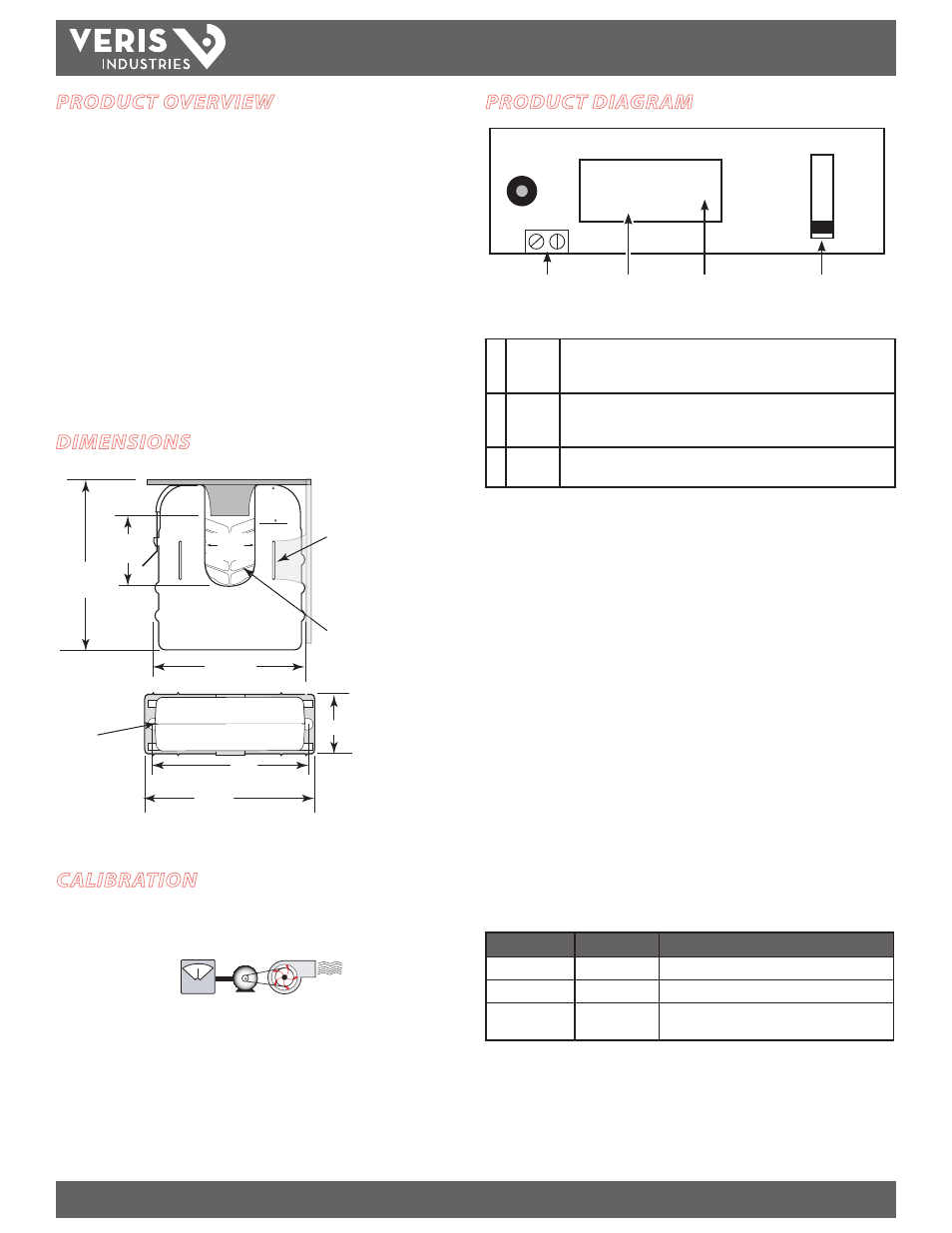
PRODUCT DIAGRAM
RESET
A
B
C
TRIP POINT
AMPS
Mem
NOW
Lrnd
N.O. Status Output
Slide Switch
LCD Value
Indicator
Slide Switch Options
A Standard ±40% of learned nominal amperage.
Max. learned nominal current is 142 A to enable an upper trip limit at or
below 200 A.
B Alternate ±60% of learned nominal amperage.
Max. learned nominal current is 125 A to enable an upper trip limit at or
below 200 A.
C On/Off
Status
Contacts remain closed while amerage is above 2.5 A at 60 Hz.
Contacts open when amperage drops below 2.5 A.
Trip limits above the 200 A maximum are not permitted.
LCD Values
If the slide switch is in position A or B, the number shown in the LCD during normal
operation cycles among the values listed below. An indicator appears to the right of
the number, indicating which value is currently visible (Mem, NOW, or Lrnd)
Mem: the trip memory, or the amperage value above or below range that
tripped the switch into alarm mode. This value remains stored in nonvolatile
memory until the H11D is reset.*
NOW: the present amperage flowing through the conductor
Lrnd: the nominal amperage conditions established when the H11D is
initially powered or reset.
* The LCD only shows the trip memory value (Mem) after a trip event has
occurred. If no trip event has occurred, the LCD only cycles between NOW and
Lrnd.
If the slide switch is in position C (on/off status only), the LCD does not cycle. The
value displayed is always the present amperage flowing through the conductor, and
the indicator remains on NOW.
Operation Modes
Mode
Output Status
LCD
Learn (30 sec)
Closed (≤ 1 Ω)
NOW indicator flashes on/off
Normal Operation Closed (≤ 1 Ω)
Display cycles between NOW and Lrnd
Alarm
Open (≥ 1 MΩ)
Display cycles among all three values: NOW, Lrnd,
and Mem *
*The LCD backlight remains off at low currents. It turns on when the current exceeds 4.5 A and
flashes during the alarm state while the current remains above 4.5 A.
Note: In rare instances, status contacts may close momentarily when the unit initially recovers
from an extended power off state (typically longer than 10 seconds) to an alarm state.