Installation guide, Installation, Hw series – Veris Industries HW SerieS Install User Manual
Page 2: Current output (2-wire, 4-20ma), Voltage output (3-wire, 0-10v)
Z202638-0W
PAGE 2
©2012 Veris Industries USA 800.354.8556 or +1.503.598.4564 / [email protected]
07123
Alta Labs, Enercept, Enspector, Hawkeye, Trustat, Veris, and the Veris ‘V’ logo are trademarks or registered trademarks of Veris Industries, L.L.C. in the USA and/or other countries.
TM
HW SEriES
inStallation GUiDE
installation
Observe precautions for handling static sensitive
devices to avoid damage to the circuitry that
is not covered under the factory warranty.
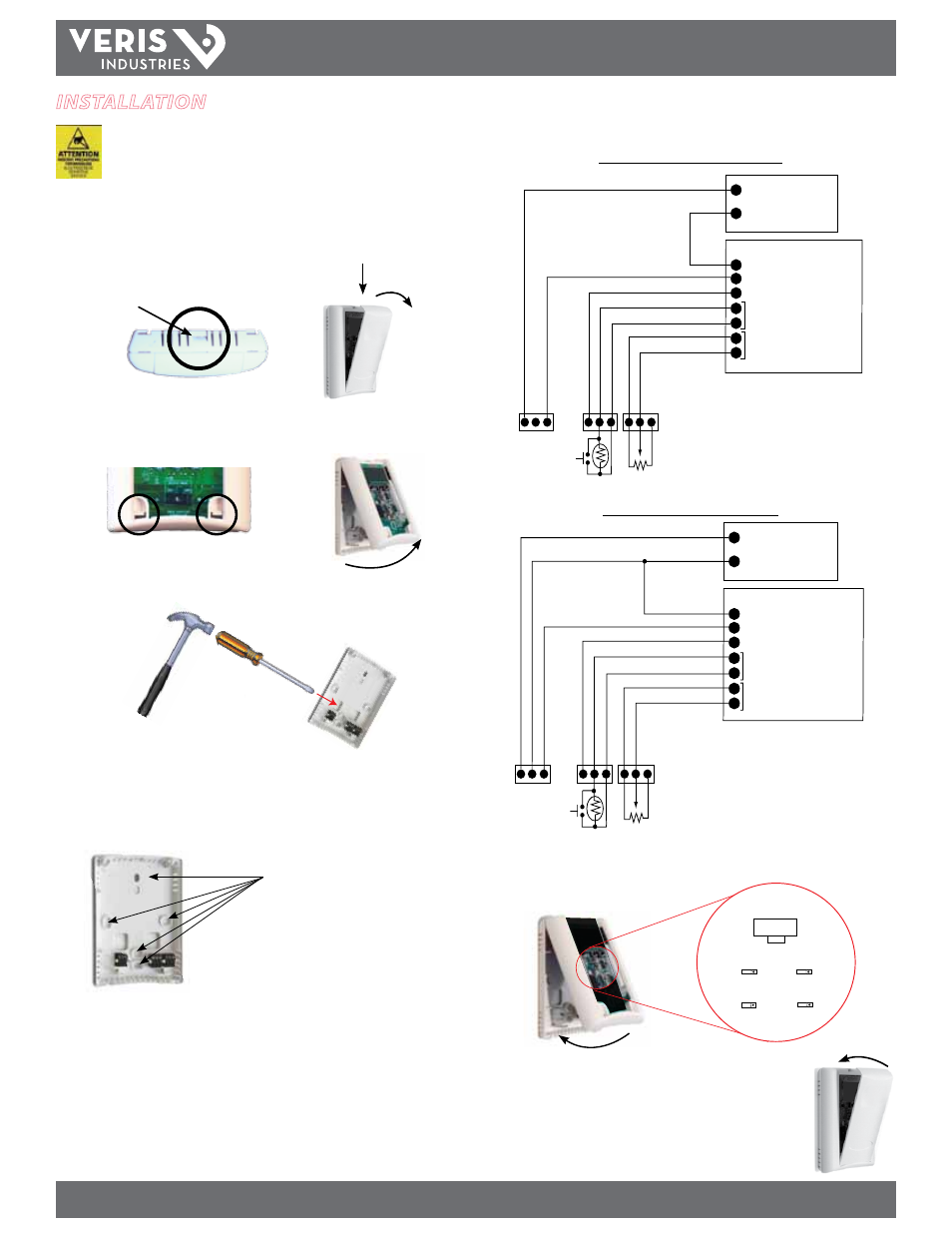
1. Locate the tab at the top of the sensor housing. Using only the minimum required
force, press this tab down and pull the cover outward from the top. Set the cover
aside.
Housing, Top View
Tab
2. Remove the backplate by unfastening the sensor from the bottom of the backplate
and pivoting the sensor outward.
3. Punch out wire opening in the backplate.
4. Position the backplate vertically on the wall, 4 ½ feet above the floor. Locate away
from windows, vents, and other sources of draft. If possible, do not mount on an
external wall, as this might cause inaccurate temperature readings.
5. Mount the backplate onto the wall using the screws provided.
Five screwholes available; use a mini-
mum of two for secure mounting.
6. Wire the backplate.
Current Output (2-Wire, 4-20mA)
POWER SUPPLY
12-24DC
CONTROL SYSTEM
COMMON
RH RETURN
T RETURN
RTD/THERMISTOR OVERRIDE
SETPOINT SLIDER
PWR (4-20 SEND
)
RH OUT (4-20 R
TN)
T OUT (4-20 R
TN)
RTD/THERMIST
OR O
VERRIDE
RTD/THERMIST
OR O
VERRIDE
SLIDER RIGHT
SLIDER LEFT
SLIDER WIPER
+
-
-
Voltage Output (3-Wire, 0-10V)
POWER SUPPLY
24 VAC/DC
CONTROL SYSTEM
COMMON
RH INPUT 0-10V
T INPUT 0-10V
RTD/THERMISTOR/OVERRIDE
SETPOINT SLIDER
PWR COMMON RH OUT
T OUT
RTD/THERMIST
OR/OVERRIDE
RTD/THERMIST
OR/OVERRIDE
SLIDER RIGHT
SLIDER LEFT
SLIDER
WIPER
+
-
-
7. Install the sensor onto the backplate and use the switch to select voltage or current
output. Output selection must be correct before applying power to the sensor.
VOLTS
OUTPUT SELECT
mA
RH OUT
10V 5V
10V 5V
50/95 32/122
C
F
T OUT
T RANGE
T SCALE
8. When the installation is complete, replace the cover and snap it
into position.