Caution, Installation guide, Operation – Veris Industries H721LC Install User Manual
Page 2: Troubleshooting, Wiring examples, Calibration/scaling, H721lc, External power sourcing panel (-common), Sinking panel (+common)
6%2)3
INSTALLATION GUIDE
H721LC
Z202941-0C
PAGE 2
©2008 Veris Industries USA 800.354.8556 or 503.598.4564 / [email protected]
09082
Alta Labs, Enercept, Enspector, Hawkeye, Trustat, Veris, and the Veris ‘V’ logo are trademarks or registered trademarks of Veris Industries, L.L.C. in the USA and/or other countries.
300A:
5A
300A
5A
10A
Controller:
CT max ÷ H721LC max
300 ÷ 10 = 30x
20mA -> 300A
300 A
opEration
The H721LC is a current transducer that senses current (amperage) in any of three
field-selectable ranges: 0-10, 0-20, or 0-40 amperes. These ranges represent the
maximum current that can be applied to the monitored conductor. The H721LC
transforms the monitored current into a 4-20mA output suitable for connection to
building controllers or other appropriate data acquisition equipment. The H721LC
requires 12-30VDC external power to generate its output.
notEs
SENSED AMPS
Selected Range*
4mA
0A
20mA
SENSOR OUTPUT
*Factory calibrated ranges selected
with the amperage range switch
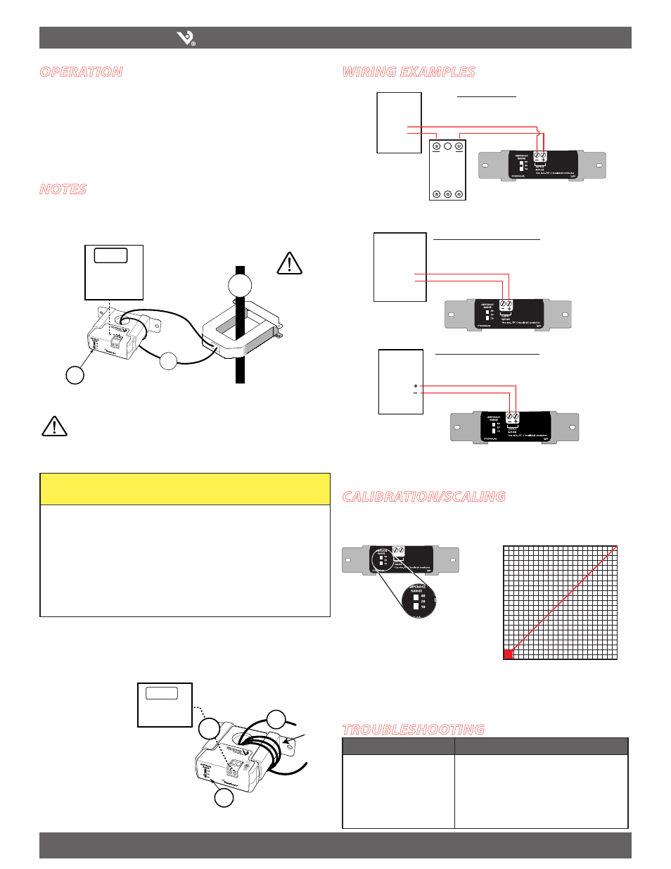
troublEshooting
For load currents less than sensor minimum rating:
Wrap the monitored conductor through the center hole and around the sensor body
to produce multiple turns through the "window." This increases the current measured
by the transducer.
• Controller must be
programmed to account
for the extra turns. e.g., if
four turns pass through
the sensor (as shown) the
normal controller reading
must be divided by 4.
< 1A (H721LC min.)
0.5A
4x
10A
Controller: 0.625 A/mA + 4mA
Amps ÷ Turns
(2A ÷ 4) = 0.5A
H721LC: 2.5A max. (4T)
7.2 mA
(2A)
0.5A
DANGER: 5A CTs can present hazardous voltages.
Install CTs in accordance with manufacturer's instructions.
Terminate the CT secondary before applying current.
H681x-5A CT
> 40A (H721LC max.)
For load currents greater than sensor maximum rating:
Use a 5 Amp (H681x series) Current Transformer (CT) as shown.
CAUTION
RISK OF EQUIPMENT DAMAGE
• Derate the product’s maximum current for the number of
turns through the sensing window using the following
formula.
Rated Max. Amps ÷ Number of Turns = Max. monitored Amps
e.g. : 30A ÷ 4 Turns = 7.5 Amps max. in monitored conductor
Failure to follow these instructions can result in overheating
and permanent equipment damage.
Problem
Solution
No Reading at Controller
•Confirm that you have 12-30VDC in series with the
sensor output terminals and the control panel analog
input.
• Confirm measured current is within the selected
range on the product.
• Check polarity of sensor output connections.
External Power
Sourcing Panel (-Common)
*A resistor can be added in parallel to convert the 4-20mA signal to a VDC signal (250 ohm=
1-5VDC); (500 ohm = 2-10VDC)
Wiring ExamplEs
DDC
CONTROLLER
PS Series
Power Supply
AI
+
+V
–
-V
NC
DDC
CONTROLLER
AI
COMM
4-20mA Out
+
–
DDC
CONTROLLER
AI
V(COM)
4-20mA
in Return
Sinking Panel (+Common)
Amperage Range
Selector Switch
calibration/scaling
Set the amperage range selector switch to a level appropriate for your load. The
H721LC is available with three choices, 0-10, 0-20, or 0-40 Amps.