Spicer Single Drive Axles Service Manual: Single Reduction & Single Reduction with Differential Lock User Manual
Page 67
64
Fastener Specifications
Ser
vice Procedure
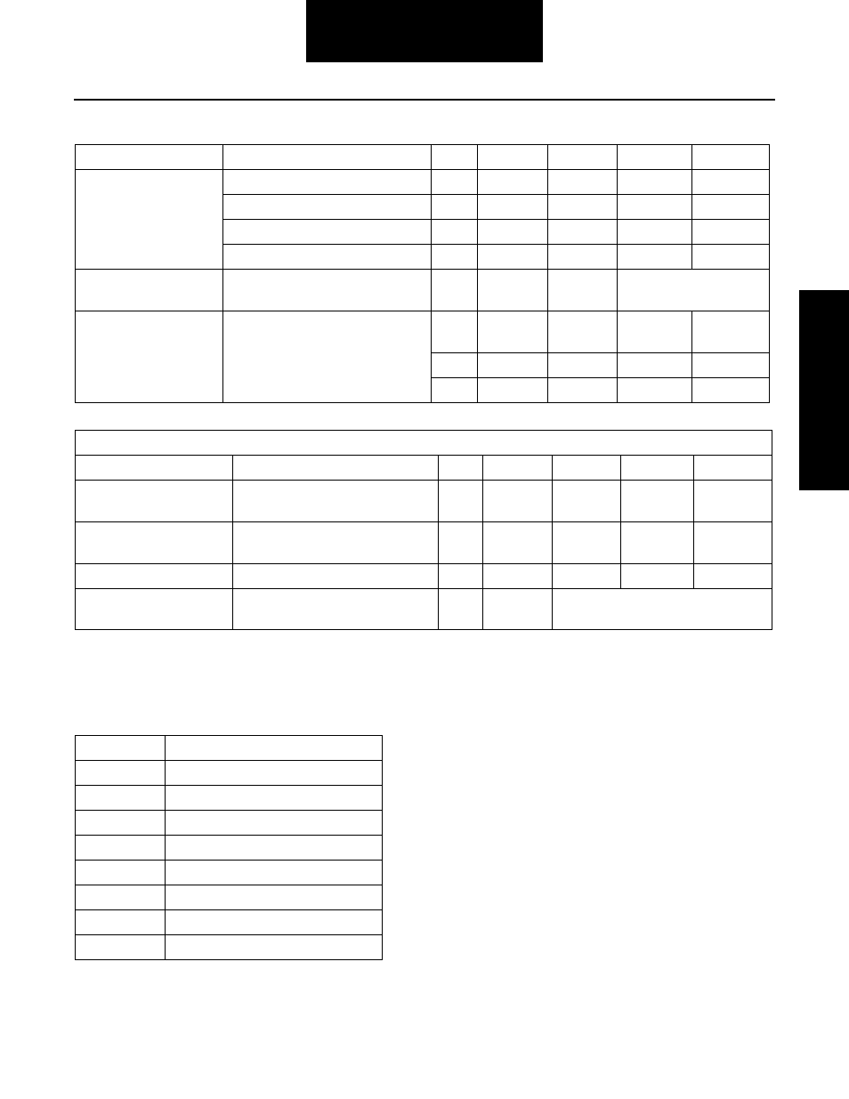
Note: In the previous charts, axle models are listed either spe-
cifically or referred to by “Series” axles. The chart below
denotes the possible models being referred to in this
manual and in the previous charts.
Note: Fasteners using self-locking thread “Patches” may be
reused if not damaged, but should be secured by a few
drops of Loctite #277 on threaded surface. Reused fas-
teners should be wiped clean of excess oil but do not
require special cleaning.
Note: Correct tightening torque values are extremely
important
to assure long Spicer life and dependable
performance. Under-tightening of attaching parts is
just as harmful as over-tightening.
Pinion Nut (Continued)
17060, 19060, 21/22 series axles
-
M36 x 1.5 55mm
575 - 703
780 - 953
21080, 23080, 26080, 30080
-
M42 x 1.5 55mm
840 - 1020 1139 - 1383
23070, 23085, 26085
-
M42 x 1.5 55mm
789 - 966
1070 - 1310
23105, 26105, 30105
All Models
All Models
All Models
All Models
All Models
-
1.75-12
2 1/4
840 - 1020 1139 - 1383
-
#1024 x 7/ 1/8 Allen
Finger Tight + 1 Turn
-
.500-20
11/16
55 - 71
75 - 96
ABS Sensor Assy Fas-
teners
8
Axle Shaft to Wheel Hub
Nut
-
.625-18
15/16
170 - 190
230 - 258
-
-
.750-16
1 1/8
285 - 345
386 - 468
Misc. Diff Lock Only Specifications
Fastener
Axle Model
Class Size
Tool Size
Lbs.-ft.
N•m
Diff Lock Shift Cylinder
Bracket Screw
1.5
Shift
Selector Switch
Fork Capscrew
All Axles where used
12.
8.8
M10- x
13mm
28 - 35
38 - 47
M12 x 1.5 24mm
.250-18
Snug to Engage Clutch Teeth
10 - 12
14 - 16
9
M8 x 1.25 6mm
Allen
12 - 15
16 - 20
Diff Lock Cylinder Ship-
ping Screw
Fastener
Axle Model
Class
Size
Tool Size
Lbs.-ft.
N•m
Series
Possible Models
15
15040
17
17060
19
19050, 19055, 19060
21
21060, 21065, 21080, 21090
22
22060, 22065
23
23070, 23080, 23085 ,23090, 23105
26
26080, 26085,26090, 26105
30
30080, 30105