Wheel differental lock ser vice procedure, Procedure – Spicer Single Drive Axles Service Manual: Single Reduction & Single Reduction with Differential Lock User Manual
Page 43
40
Wheel Differental lock
Ser
vice Procedure
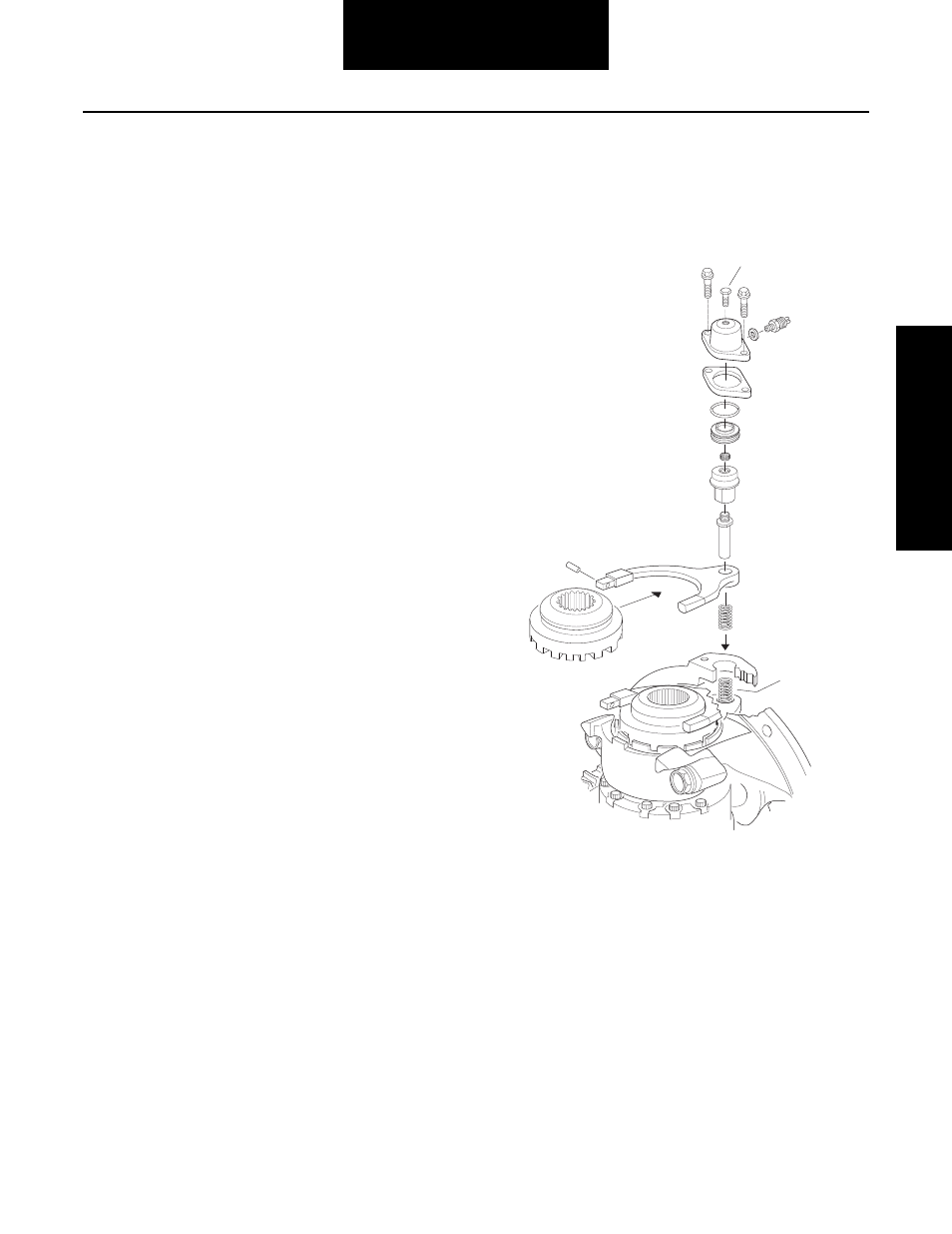
Install and Adjust Differential Lock - Type 2 Axles
Note: With differential carrier completely assembled and
adjusted, install differential lock as follows:
Procedure -
1.
Install fixed curvic clutch on splined hub of flanged
differential case, then install snap ring.
2.
If shift fork and sliding curvic clutch are disassem-
bled, engage fork with clutch hub, and install spring
pin in the long leg of the fork. See illustration for fork
mounting position on clutch.
3.
Position compression spring, shift fork and clutch
assembly in shift opening of the carrier. Align pilot
hole of shift fork with pilot hole of carrier. Install
pushrod, engaging shift fork head and compression
spring in carrier.
Note: The shift cylinder is serviced only as an assembly. How-
ever, if the cylinder is disassembled and parts are ser-
viceable, assemble as described in Steps 4 and 5.
4.
Install new O-ring on piston.
5.
Lubricate piston and O-ring with silicone grease and
install piston assembly in cylinder. Position piston
with small diameter hub toward closed end of cylin-
der.
6.
Screw piston driver on pushrod.
7.
Tighten piston driver until shift fork clutch is approx-
imately .030 of an inch from the fixed clutch.
8.
Push down by hand on the piston driver, both
clutches must be completely engaged.
9.
Install set screw in piston driver and torque to 12-15
lbs.ft. (16-20 N•m).
10. Trial fit, install piston cover assembly. Hand tighten
cap screws.
11. Screw in manual engagement screw by hand
approximately 1 inch or until snug fit (light resis-
tance pressure is felt). Both clutches must be com-
pletely engaged.
12. Remove manual engagement screw clutches until
completely disengaged.
•
Repeat above procedure if clutches are not
completely disengaged.
Note: Fork adjustment is correct when curvic clutch teeth are
fully engaged with the fork free when moved by hand.
When air pressure is released or the manual bolt is
removed, the shift assembly should disengage freely.
13. When adjustment is complete, torque fasteners to
28-35 lbs.ft. (38-47 N•m).
Sliding
clutch
Clutch
fork
Insert
spring
here
Spring
Pushrod
Pin
Piston
driver
Setscrew
Piston
O-ring
Switch
Manual
engagement
screw
Capscrew
Washer
Gasket