Warning, Wheel differental lock, Procedure – Spicer Single Drive Axles Service Manual: Single Reduction & Single Reduction with Differential Lock User Manual
Page 44
41
Wheel Differental lock
Install and Adjust Differential Lock - Type
2 Axles Continued
Procedure -
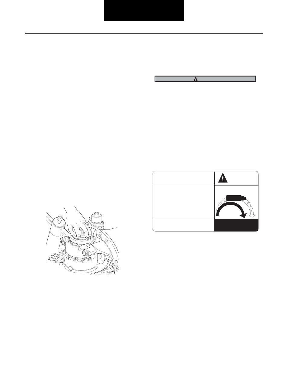
1. Install selector switch in cylinder cover. Torque
switch to 10-12 lbs.ft (14-16 N•m).
Note: Effective July 1, 1996, Dana will standardize on the
selector switch and wiring harness. Reference Bulletin
ABIB-9609. Types 1 and 2 switches with 12 mm threads
will be discontinued. The selector switch and wiring har-
nesses are interchangeable with each other.
Check Selector Switch Operation: Check switch electrically
with an ohmmeter or continuity tester. Switch should close
(show continuity) when clutches are engaged and should
open (no continuity) when clutches are disengaged
Install Differential Carrier Assembly in Axle Housing: The
differential lock must be engaged and held in the engaged
position for installation of carrier assembly in axle housing.
This can be accomplished by one of the following two meth-
ods:
Air Pressure Engagement: Using an auxiliary air line,
apply 80-120 psi air pressure to shift cylinder air port to
engage clutch.
Manual Engagement: Install an M12x1.5 bolt, over
38mm (1.5") long, in the cylinder air port to manually
engage the clutches
With clutches engaged, grasp fork long leg between thumb
and forefinger. Move fork back and forth to check for free
movement.
Some GM models use a .250 x 18 NPSM (128642), manual
engagement bolt.
Note: Hand-tighten the bolt, over-torquing may cause damage
to the shift unit. To facilitate hand tightening, lubricate
bolt threads with axle lube.
2. Complete the installation of the carrier following
instructions for your specific axle.
When installing axle shafts, make sure the long/splined
shaft is installed in the shift unit side of differential carrier
3. After carrier and axle shaft installation, discon-
nect auxiliary air line or remove bolt from cylin-
der air port. Connect vehicle air supply to shift
cylinder and electrical lead wires to selector
switch
4. Check differential lock operation from driver’s
cab before releasing vehicle for service.
5. Verify the driver caution label is in the vehicle
cab and is easily visible by the driver.
CAUTION
THIS VEHICLE IS EQUIPPED WITH
THE DRIVER CONTROLLED WHEEL
DIFFERENTIAL LOCK.
Engage only when traction is poor
Do not engage when tires are slipping
Disengage when going down hill
Disengage at speeds above 25 mph
Steering will be adversely
affected when engaged
For further information
consult your owners manual
or Spicer publication AXDR-0130
DISENGAGED
DRIVE CARFULLY
WHEN ENGAGED
12804
5
ENGAGED
WARNING
Warning Label 128045