1 input setup – Soft dB Opus Suite Data Logger Module User Manual
Page 12
11
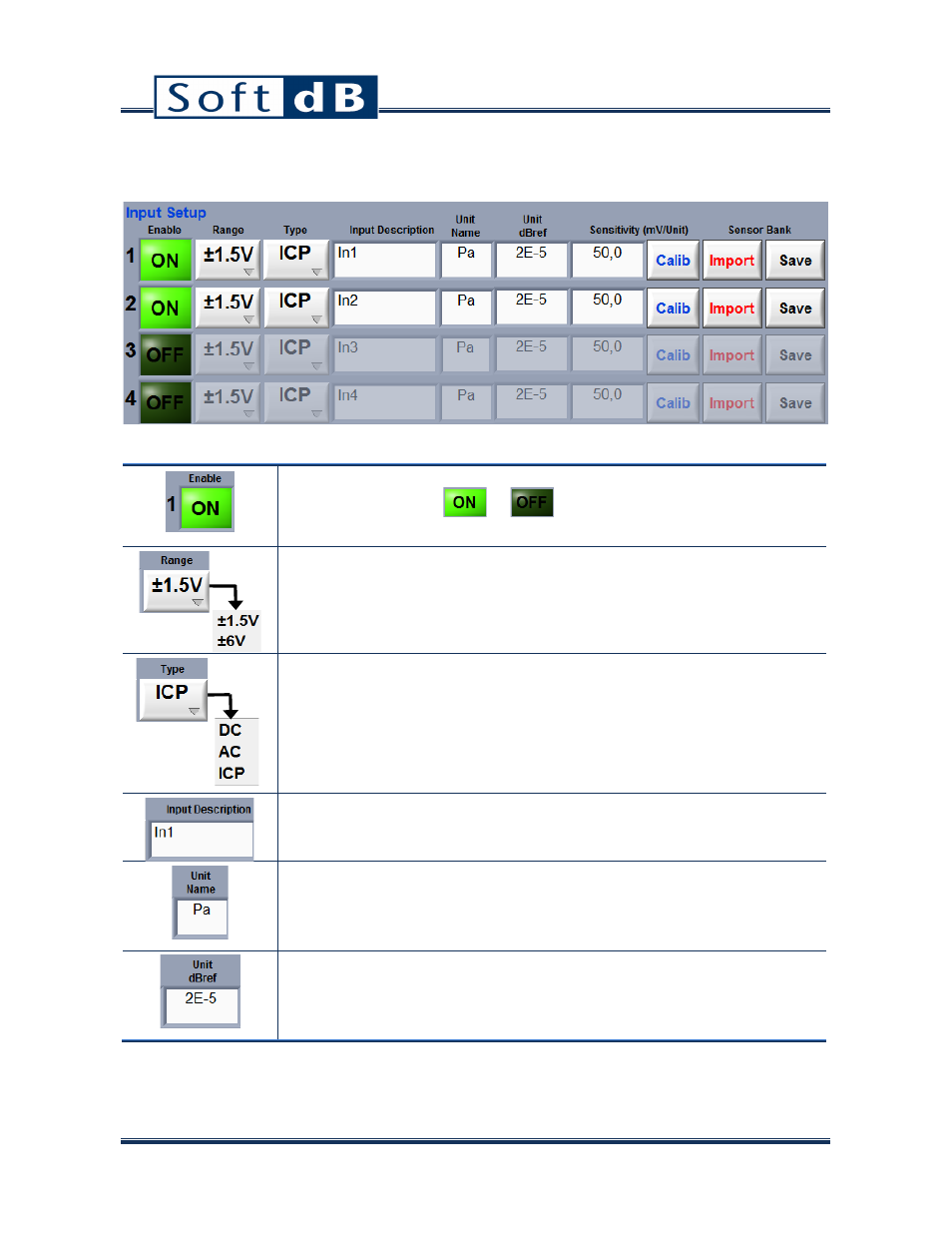
6.1 Input Setup
Input Setup
Input Enable
Set the input switch to
or
to enable or disable the
corresponding input. 1 to 4 inputs can be used simultaneously.
Input Range:
• +/- 1.5 volt: low range
• +/- 6 volts: high range (only available on inputs 1 and 2)
Input Type
• DC input: both AC and DC components are present in the signal.
• AC input: the DC component is filtered from the input signal.
• ICP input: polarized for an ICP sensor and DC component is filtered.
• The DC filter is a high-pass filter at Fc=0.5Hz. Common ICP sensors
are ICP microphones and accelerometers.
Input Description
This text control allows the user to identify the input. This information has no
impact on the behaviour of the acquisition system.
Unit name
This text control is used by the acquisition system for the label of the global
level, time and spectrum graphs. For instance, if a Pa unit is specified by the
user for input #1, the Y label of the Spectrum will be dB(Parms^2).
Unit dBref
The dB reference value is used by the interface for dB computation. For
acoustic measurement with a microphone, the standard dB reference value is
2E-5.