5 serial handshaking, 5 example setup, Figure 3-5. example magnet specification sheet – American Magnetics 420 Power Supply Programmer User Manual
Page 68: Example setup, Figure 3-5, Example magnet specification sheet, H 3.2.5 on, Operation, Rev. 7
50
Operation
Example Setup
3.2.4.5 Serial Handshaking
Specifies whether the serial interface uses no handshaking or
software handshaking (commonly referred to as XON/XOFF).
Hardware handshaking is not supported. Use the
237,21
key to
cycle between values. The default setting is no handshaking.
3.2.5 Example Setup
As a precursor to operating a superconducting magnet with the Model 420
programmer and power supply, all of the setup items should be reviewed
and set if necessary with appropriate values for the connected
superconducting magnet.
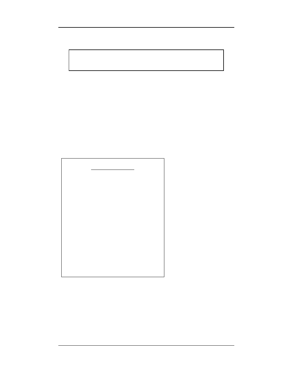
Figure 3-5 shows an exam-
ple magnet specifications
sheet. Several parameters
needed to operate the mag-
net are specified. These
values should be entered
into the appropriate setup
menu of the Model 420.
For the purposes of this
example, the AMI Model
12100PS power supply
without an energy
absorber will be assumed,
since rated current for the
example magnet is
76.23 A.
The current limit
accessible in the Load
setup submenu should be
set to the rated current to
prevent accidental
operation of the magnet
above rated current/field. The magnet specification sheet also indicates
whether a persistent switch is installed and provides the recommended
heating current. The persistent switch information is entered in the load
setup submenu.
$ × 6HULDO +DQGVKDNLQJ
9V
1RQH
6: ;21;2))
MAGNET SPECIFICATIONS
AMI JOB #10501 MAGNET #10228
Type: Solenoid
MODEL: A9020-3
TEST DATE: April 22, 2002
Rated Central Field @ 4.2K ---------------
90 KG
Rated Current ----------------------------
76.23 Amps
Maximum Test Field @ 4.2K * --------------
92 KG
Measured Field to Current Ratio ----------
1180.6 Gauss/Amp
Homogeneity over 1 cm DSV ----------------
+/- 0.1%
Measured Inductance ----------------------
9.8 Henries
Charging Voltage (Used in test) ----------
2.0 Volts
Axial Clear Bore -------------------------
2.0 inches
Overall Length (flange to flange) --------
8.0 inches
Maximum Outside Diameter -----------------
4.6 inches
Weight -----------------------------------
28 lbs.
Recommended Persistent Switch Heater Current -----
46 mA
Persistent Switch Heater Nominal Resistance** ----
69 Ohms
Magnet Resistance in Parallel with Switch** ------
21 Ohms
Mounting: 3 Holes tapped for 10-32 on top and bottom flanges,
equally spaced on a 3.00 inch B.C.D.
* Magnet not warranted for operation above
90
KG field.
** All resistance measurements made at room temperature.
Figure 3-5. Example magnet specification sheet.