Appendix, A.1 magnet station connectors, Table a-1. connectors j7a and j7b pin definitions – American Magnetics 420 Power Supply Programmer User Manual
Page 123: Table a-1, Connectors j7a and j7b pin definitions
105
Appendix
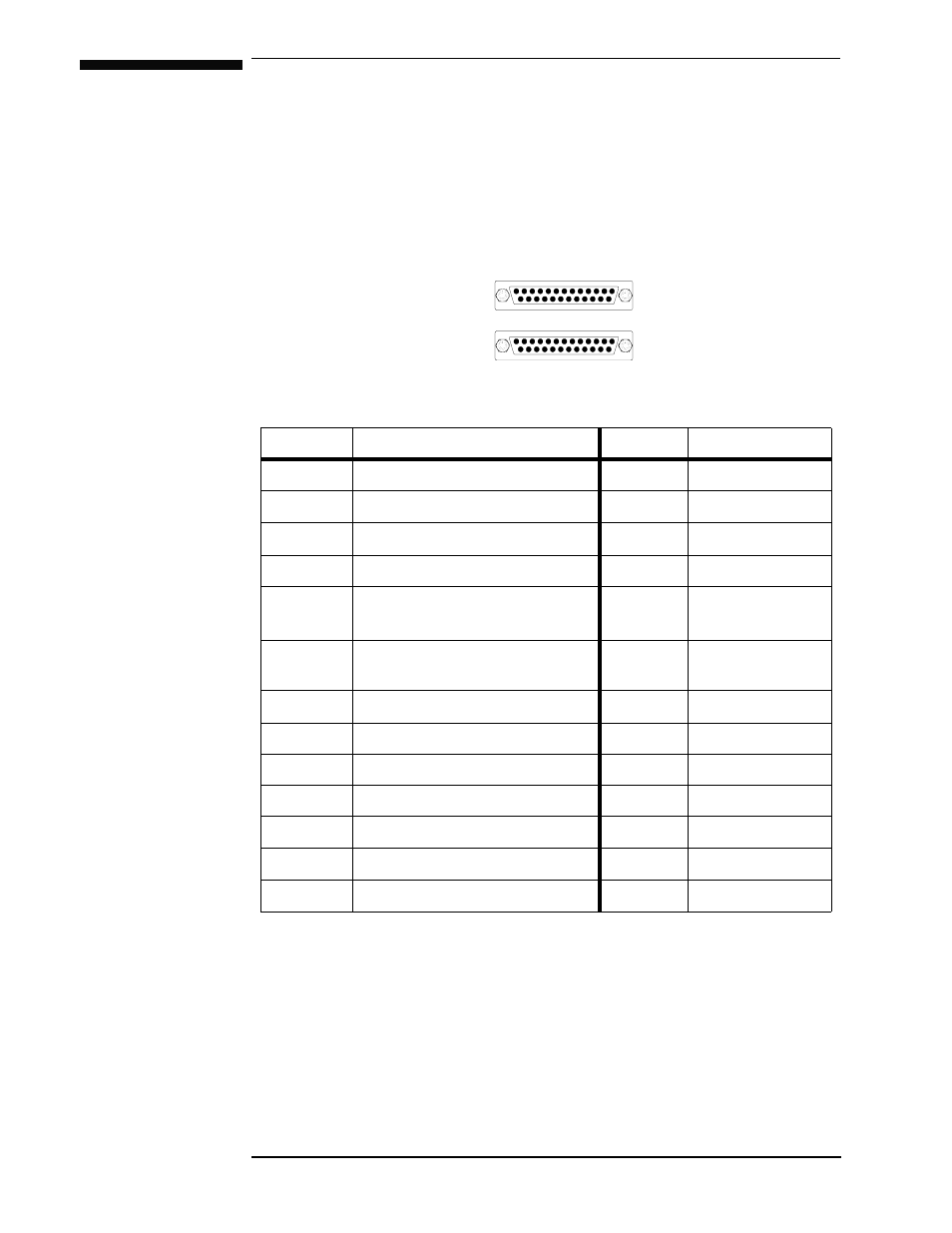
A.1 Magnet Station Connectors
The two 25-pin D-sub female Magnet Station Connectors are identically
wired and connected pin-for-pin internally. Spare wires may be used for
custom coil taps or other signals.
The connectors provide an interface for connecting a single integrated
instrumentation cable from the magnet support stand to the Model 420.
The Model 420 can then be used to distribute the signals to the
Table A-1. Connectors J7A and J7B pin definitions.
Pin
Function
Pin
Function
1
LHe Sensor I+ (Red)
14
Spare
2
LHe Sensor I
−
(Black)
15
Spare
3
LHe Sensor V
−
(Yellow)
16
Spare
4
LHe Sensor V+ (Blue)
17
Spare
5
Temperature Sensor I+ (Red)
18
External Switch
Heater Current
a
a. See discussion on page 61 for further details on the use of an optional external power
supply for heating the persistent switch.
6
Temperature Sensor I
−
(Black)
19
External Switch
Heater Current
7
Temperature Sensor V
−
(Yellow)
20
Spare
8
Temperature Sensor V+ (Blue)
21
Spare
9
Persistent Switch Heater (Red)
22
Spare
10
Persistent Switch Heater (Black)
23
Spare
11
Magnet Voltage Tap V+ (Yellow)
24
Spare
12
Magnet Voltage Tap V
−
(Blue)
25
Spare
13
Spare
H6BI@UÃTU6UDPI
8PII@8UPST
E&6
E&7