2 dual-quadrant operation, Figure 1-3. dual-quadrant magnet system, 3 simulated four-quadrant operation – American Magnetics 420 Power Supply Programmer User Manual
Page 28: Figure 1-4. simulated four-quadrant magnet system, Dual-quadrant operation, Simulated four-quadrant operation, Figure 1-3, Dual-quadrant magnet system, Figure 1-4, Simulated four-quadrant magnet system
10
Introduction
Operating Characteristics
1.5.2
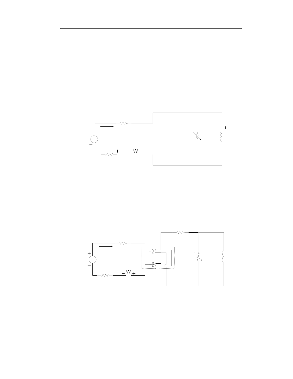
Dual-Quadrant Operation
In the dual-quadrant programmer-power supply system, as illustrated in
Figure 1-3, an energy absorber is added which allows the magnetic energy
to be converted to thermal energy, thereby allowing much faster magnetic
field reduction. This represents operation in quadrants 1 and 4 of Figure
1-1. The disadvantage to this type of system is that whenever there is
current flowing in the magnet, there is energy being dissipated in the
energy absorbing element, which is sometimes a significant portion of the
power required to operate the system.
1.5.3
Simulated Four-Quadrant Operation
In the simulated four-quadrant programmer-power supply system, as
show in Figure 1-4, a mechanical current reversing switch is included,
usually in the energy absorber. This allows the current in the magnet to be
reversed after the current has first been reduced to zero. These systems
usually incorporate some type of electronic interlock to ensure large
amounts of current are not interrupted when the reversing sequence is
initiated. The disadvantages of this system are energy inefficiencies and
the finite period of time required to pause at zero magnet current before
Magnet
Coil(s)
Persistent
Switch
(optional)
Misc. Line Losses
Model 420
Shunt
Energy
Absorber
V
Unipolar
Power Supply
Current
Figure 1-3. Dual-Quadrant Magnet System
Magnet
Coil(s)
Persistent
Switch
(optional)
Misc. Line Losses
Model 420
Shunt
Energy
Absorber
V
Unipolar
Power Supply
Current
Current
Reversing
Switch
Misc. Line Losses
Figure 1-4. Simulated Four-Quadrant Magnet System