Bosch GWS 18-125 V-LI Professional User Manual
Page 20
English |
21
Bosch Power Tools
1 609 92A 01F | (10.1.13)
Clean the grinder spindle
8 and all parts to be mounted.
For clamping and loosening the grinding tools, lock the grind-
er spindle with the spindle lock button
2.
Actuate the spindle lock button only when the grinder
spindle is at a standstill. Otherwise, the machine may be-
come damaged.
Grinding/Cutting Disc
Pay attention to the dimensions of the grinding tools. The
mounting hole diameter must fit the mounting flange without
play. Do not use reducers or adapters.
When using diamond cutting discs, pay attention that the di-
rection-of-rotation arrow on the diamond cutting disc and the
direction of rotation of the machine (see direction-of-rotation
arrow on the machine head) agree.
See graphics page for the mounting sequence.
To fasten the grinding/cutting disc, screw on the clamping nut
13 and tighten with the two-pin spanner; see Section “Quick-
clamping Nut ”.
After mounting the grinding tool and before switching
on, check that the grinding tool is correctly mounted
and that it can turn freely. Make sure that the grinding
tool does not graze against the protection guard or oth-
er parts.
A plastic part (O-ring) is fitted around
the centring collar of mounting flange
11. If the O-ring is missing or dam-
aged, the mounting flange 11 must be
replaced before resuming operation.
Flap Disc
For operations with the flap disc, always mount the
hand guard 18.
Rubber Sanding Plate
For operations with the rubber sanding plate 19, al-
ways mount the hand guard 18.
See graphics page for the mounting sequence.
Screw on the round nut
21 and tighten with the two-pin span-
ner.
Cup Brush/Disc Brush
For operations with the cup brush/wheel brush, always
mount the hand guard 18.
See graphics page for the mounting sequence.
The cup brush/disc brush must be able to be screwed onto
the grinder spindle until it rests firmly against the grinder
spindle flange at the end of the grinder spindle threads. Tight-
en the cup brush/disc brush with an open-end spanner.
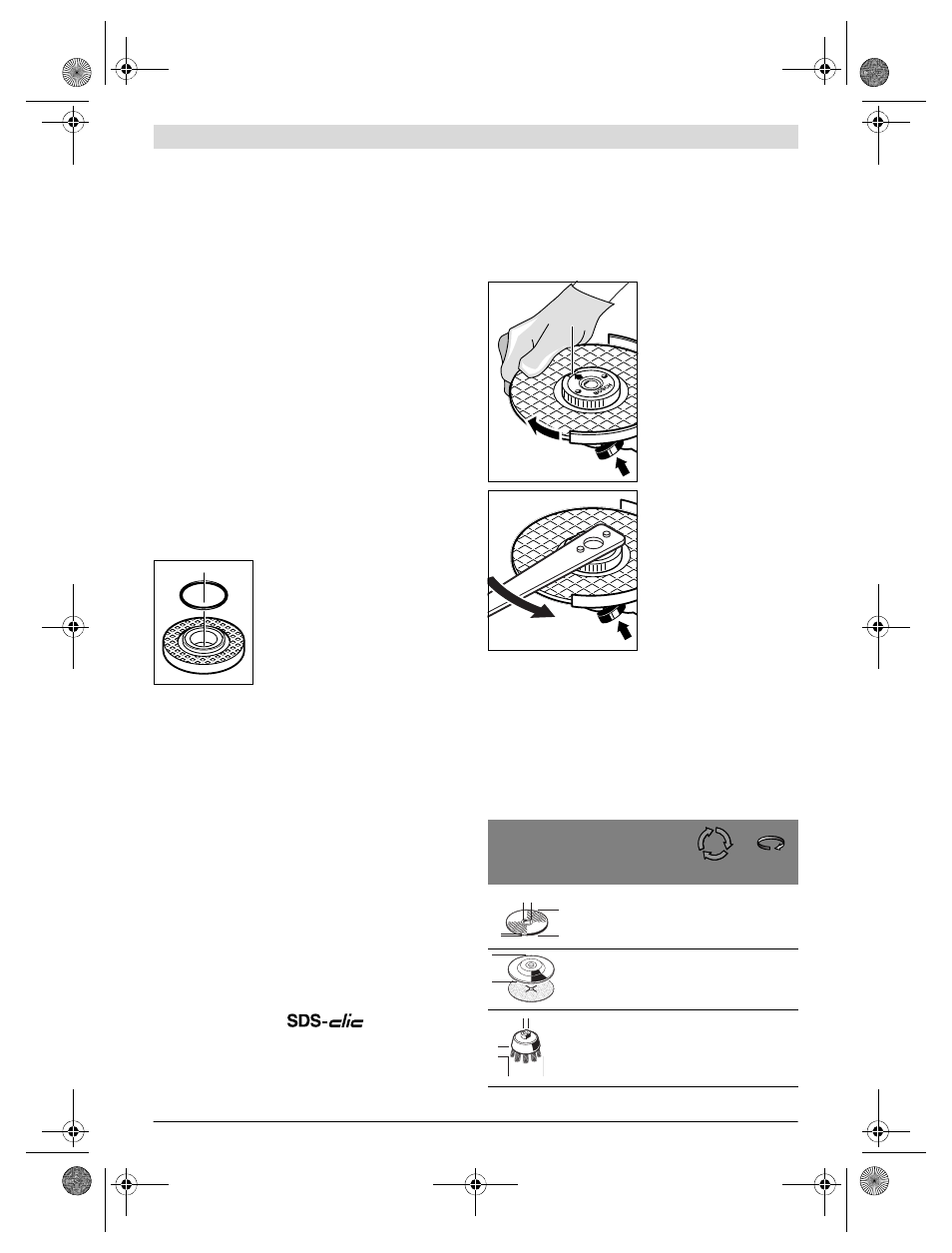
Quick-clamping Nut
For convenient changing of grinding tools without the use of
additional tools, you can use the quick-clamping nut
14 in-
stead of the clamping nut
13.
The quick-clamping nut 14 may be used only for grind-
ing or cutting discs.
Use only a flawless, undamaged quick-clamping nut 14.
When screwing on, pay attention that the side of the
quick-clamping nut 14 with printing does not face the
grinding disc; the arrow must point to the index mark
28.
Lock the grinder spindle with
the spindle lock button
2. To
tighten the quick-clamping
nut, firmly turn the grinding
disc in clockwise direction.
A properly attached, undam-
aged quick-clamping nut can
be loosened by hand when
turning the knurled ring in an-
ticlockwise direction.
Never loosen a tight quick-
clamping nut with pliers. Al-
ways use the two-pin span-
ner. Insert the two-pin span-
ner as shown in the
illustration.
Approved Grinding Tools
All grinding tools mentioned in these operating instructions
can be used.
The permissible speed [min
-1
] or the circumferential speed
[m/s] of the grinding tools used must at least match the values
given in the table.
Therefore, observe the permissible
rotational/circumferen-
tial speed on the label of the grinding tool.
max.
[mm]
[mm]
D
b
d
[min
-1
]
[m/s]
115
125
6
6
22.2
22.2
10000
10000
80
80
115
125
–
–
–
–
10000
10000
80
80
75
30
M 14
10000
45
28
b
d
D
D
D
b
d
OBJ_BUCH-1102-005.book Page 21 Thursday, January 10, 2013 11:03 AM