English – ASRock Z68 Extreme3 Gen3 User Manual
Page 33
33
ASRock Z68 Extreme3 Gen3 Motherboard
English
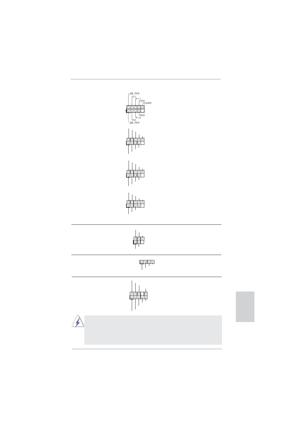
USB 2.0 Headers
Besides four default USB 2.0
(9-pin USB6_7)
ports on the I/O panel, there
(see p.2 No. 29)
are four USB 2.0 headers on
this motherboard. Each
USB 2.0 header can support
two USB 2.0 ports.
(9-pin USB8_9)
(see p.2 No. 28)
(9-pin USB10_11)
(see p.2 No. 27)
(9-pin USB12_13)
(see p.2 No. 25)
1
USB_PWR
P-8
GND
DUMMY
USB_PWR
P+8
GND
P-9
P+9
1
USB_PWR
P-10
GND
DUMMY
USB_PWR
P+10
GND
P-11
P+11
Infrared Module Header
This header supports an
(5-pin IR1)
optional wireless transmitting
(see p.2 No. 33)
and receiving infrared module.
1
IRTX
+5VSB
DUMMY
IRRX
GND
Consumer Infrared Module Header
This header can be used to
(4-pin CIR1)
connect the remote
(see p.2 No. 30)
controller
receiver.
1
ATX+5VSB
IRTX
GND
IRRX
1. High Defi nition Audio supports Jack Sensing, but the panel wire on
the chassis must support HDA to function correctly. Please follow the
instruction in our manual and chassis manual to install your system.
2. If you use AC’97 audio panel, please install it to the front panel audio
header as below:
J_SENSE
OUT2_L
1
MIC_RET
PRESENCE#
GND
OUT2_R
MIC2_R
MIC2_L
OUT_RET
Front Panel Audio Header
This is an interface for front
(9-pin HD_AUDIO1)
panel audio cable that allows
(see p.2 No. 34)
convenient connection and
control of audio devices.
1
USB_PWR
P-13
P+13
USB_PWR
P-12
P+12
GND
GND
DUMMY