ACU-RITE MILLPWR Auxiliary User Manual
Page 17
AMI Reference Manual
14
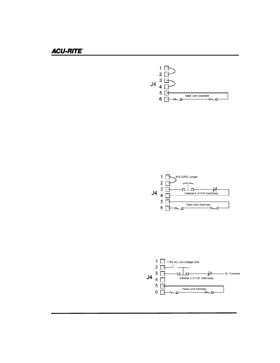
Fig. 4
Fig. 5
Figure 4
illustrates how a table
limit switch can be wired into the
emergency stop circuitry. Notice that
the switches have been connected to
pins 5 and 6, which are the table
limit switch contacts (refer to Table
3). Because the table limit connec-
tions operate on internal 12V DC
power, it’s important to use a table
limit switch with a 12V DC @
100mA minimum rating. Do not
apply voltage directly to pins 5 or
6 on the J4 connector.
Figure 5
shows how an external
Emergency Stop button can use the
AMI circuit board as its power
source (the table limit switches are
shown for completeness). 115V AC
is provided between pins 1 and 4 of
J4 for the internal emergency stop
relay coil.
Figure 6
shows how the external
emergency stop can be wired directly
into an external 115V AC circuit.
When wiring the Emergency Stop button, use a switch with a 115V AC @
100mA minimum rating. (Do not use this circuit to power any external
devices.)
Fig. 6
There are two options for wiring the additional Emergency Stop button. It can be
wired directly to the AMI’s circuit board as a contact closure, or it can be wired
into an external 115V AC system.