Ami reference manual, Emergency stop inputs (j4) – ACU-RITE MILLPWR Auxiliary User Manual
Page 16
AMI Reference Manual
13
Emergency Stop Inputs (J4)
The J4 connector is commonly used to:
•
Add table limit switches to the emergency stop circuitry
•
Add an Emergency Stop button to the emergency stop circuitry
Table 3 (J4)
Pin #
Description
1
2
3
4
5
6
115V (for E-stop relay coil only)
Auxiliary E-stop relay coil (K1)
Auxiliary E-stop relay coil (K1)
AC Common (for E-stop relay coil only)
Table limit switch contact
Table limit switch contact
An emergency stop condition normally occurs when the system overheats, a
fault occurs, or when the Emergency Stop button on the
MILLPWR
operator
console is pressed. The AMI gives you the option of adding table limit switch-
es and another Emergency Stop button into the system’s emergency stop cir-
cuitry. When an emergency stop is activated,
MILLPWR
will immediately shut
off the system’s motors, shut off any external devices that are connected to the
AMI, and stop all machine movement.
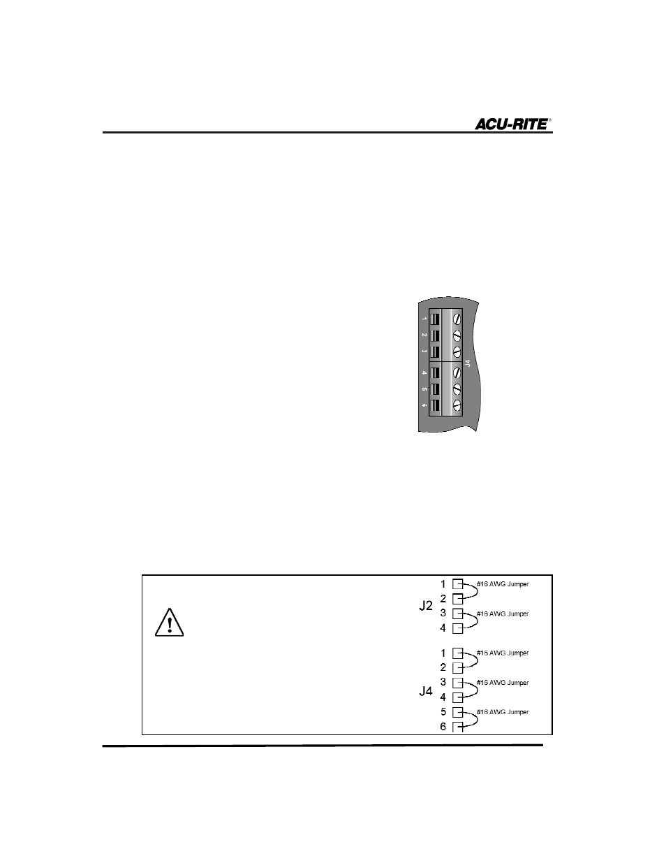
If you are not using the J2 or J4 connec-
tor on the AMI, you must wire a jumper
at this time to close the circuitry.
Otherwise, when you power on
MILLPWR
and the AMI, an emergency stop condi-
tion will automatically occur and
neither system will run.