Picc interface description, Atr generation, Atr format for iso 14443 part 3 piccs – ACS AET62 NFC Reader with Fingerprint Sensor User Manual
Page 8: Table 2
4.0. PICC Interface Description
4.1. ATR Generation
If the reader detects a PICC, an ATR will be sent to the PCSC driver to identify the PICC.
4.1.1.
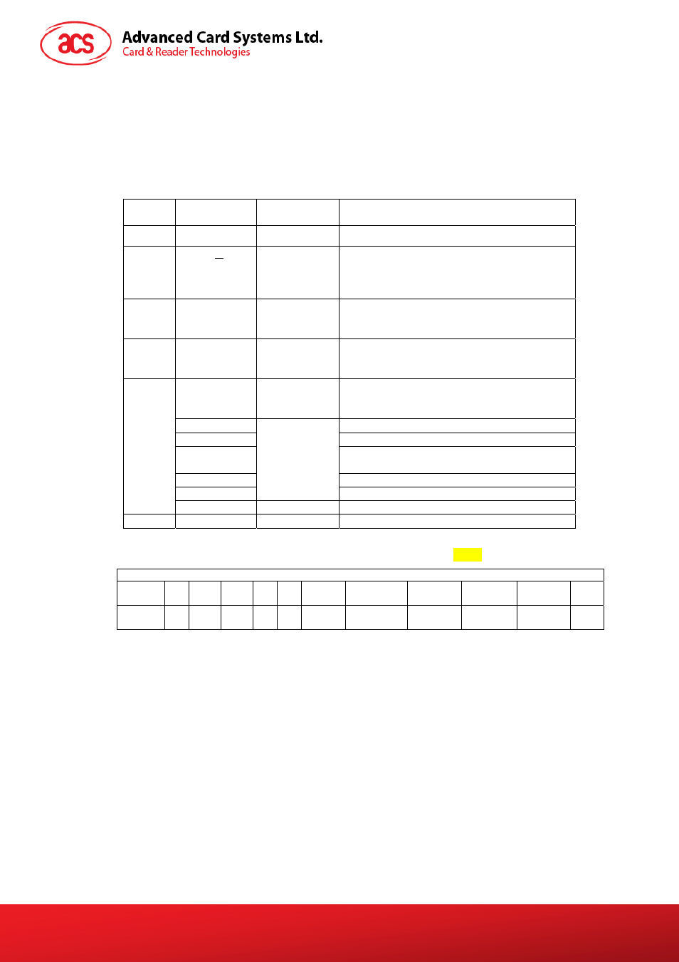
ATR format for ISO 14443 Part 3 PICCs
Byte
Value
(Hex)
Designation Description
0 3B
Initial
Header
1 8N
T0
Higher nibble 8 means: no TA1, TB1, TC1
only TD1 is following.
Lower nibble N is the number of historical
bytes (HistByte 0 to HistByte N-1)
2
80
TD1
Higher nibble 8 means: no TA2, TB2, TC2
only TD2 is following.
Lower nibble 0 means T = 0
3
01
TD2
Higher nibble 0 means no TA3, TB3, TC3,
TD3 following.
Lower nibble 1 means T = 1
80
T1
Category indicator byte, 80 means A status
indicator may be present in an optional
COMPACT-TLV data object
4F
Application identifier Presence Indicator
0C Length
RID Registered
Application Provider Identifier
(RID) # A0 00 00 03 06
SS
Byte for standard
C0 .. C1
Tk
Bytes for card name
4
To
3+N
00 00 00 00
RFU
RFU # 00 00 00 00
4+N
UU
TCK
Exclusive-oring of all the bytes T0 to Tk
Table 2: ATR format for ISO 14443 Part 3 PICCs
Example: ATR for MIfare 1K = {3B 8F 80 01 80 4F 0C
A0 00 00 03 06
03
00 01 00 00 00 00 6A}
ATR
Initial
Header
T0 TD1 TD2 T1 Tk Length RID
Standard Card
Name
RFU TCK
3B
8F
80 01 80
4F
0C
A0 00 00
03 06
03
00 01
00 00 00
00
6A
Where:
Length (YY)
=
0C
RID
=
A0 00 00 03 06
(PC/SC Workgroup)
Standard (SS)
= 03 (ISO14443A, Part 3)
Card Name (C0 .. C1)
= [00 01] (Mifare 1K)
Where, Card Name (C0 .. C1)
00 01: Mifare 1K
00 02: Mifare 4K
00 03: Mifare Ultralight
00 26: Mifare Mini
….
F0 04: Topaz and Jewel
F0 11: FeliCa 212K
F0 12: FeliCa 424K
…
FF [SAK]: Undefined
Document Title Here
Document Title Here
Document Title Here
AET62 Reference Manual
Version 1.00
Page 8 of 35
www.acs.com.hk