Wiring connections, Wiring examples – Acroprint HandPunch 4000 User Manual
Page 80
Appendix C - Old Board Configuration
78
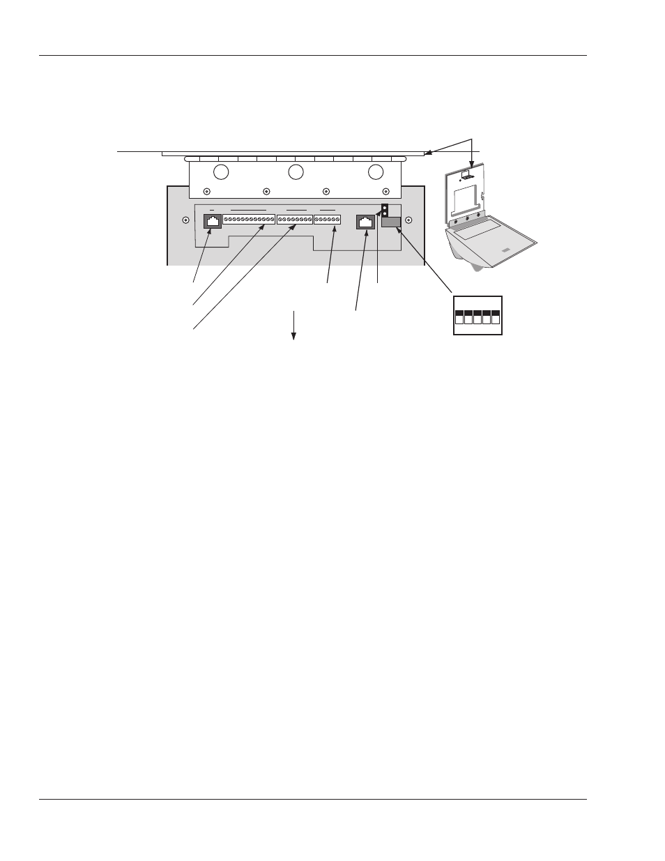
Figure 13-3: Wiring Connections and Dip Switches
Wiring Connections
Once the HandPunch is attached to the wall plate the wiring connections to the
HandPunch can be made (see Figure 13-3 below).
Wiring Examples
The following Tables provide the pin outs for the terminal strips on the
HandPunch.
• “Table 14” on page 79 provides the pinouts for TS-2 – Input Connections.
• “Table 15” on page 79 provides the pinouts for TS-3 – Card Reader and Output
Connections.
• “Table 16” on page 80 provides the pinouts for the RJ-45/RS-232 Serial Printer
or Host Computer Connection.
• “Table 17” on page 81 provides the pinouts for the RJ-11/RS-422 HandPunch-
to-HandPunch Network Connection.
The following Figures provide pinout diagrams for the RJ connectors.
• Figure 13-4 on 81 provides the pinouts for J3, the RJ-11/RS-422
Network Connection.
• “Figure 13-5” on page 81 provides the pinouts for J8, the RJ-45/RS-232 Serial
Printer Connection.
WALL
O N
O F F
5 4 3 2 1
RS-232 RJ-45
TS-3 Terminals 26 to 15
TS-2 Terminals 14 to 7
TS-1 Terminals 6 to 1
Optional Modem
or Ethernet Jack
Dip Switches
Wall Plate
Top of
Terminal
Top of Hand Reader
14
7 6
1
15
26
Backup Battery
Jumper
8 1