Grounding, Switch inputs outputs, Earth ground connection pins – Acroprint HandPunch 4000 User Manual
Page 79
HandPunch 3000/4000 Manual
77
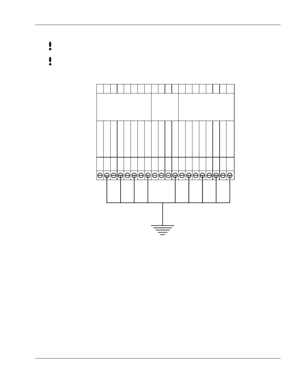
Figure 13-2: Earth Ground Connection Terminals
There are two standard methods for providing earth grounding to HandPunch
units:
• earth grounding all units (see 15)
• carrying an earth ground to each unit (see 16)
Earth ground all units when there is a good earth ground source near each unit
and/or when there are very long cable runs between units.
Carry an earth ground to each unit when there are no earth grounds convenient
to the unit and the unit’s power supply is floating.
Grounding
Terminal 1 and the center pin of jack J12 are connected together. Terminal 2 and
the sleeve of jack J12 are connected together.
Use any one of the following ground terminals to make the earth ground
connection: 8, 10, 12, 14, 18, 20, 22, 24, or 26. Do
NOT use terminal 2 to
establish the earth ground connection; terminal 2 is not directly connected to
ground.
7 8 9 10 11 12 13 14 15 16 17 18 19 20 21 22 23 24 25 26
7
8
9
10
11
12
13
14
15
16
17
18
19
20
21
22
23
24
2625
SWITCH INPUTS
OUTPUTS
CARD
READER
INPUT
REX SWITCH
GR
OUND
DOOR SWITCH
GR
OUND
A
UX IN
1
GR
OUND
GR
OUND
GR
OUND
GR
OUND
GR
OUND
GR
OUND
GR
OUND
A
UX IN
2
+5
VD
C OUTPUT
D
AT
A
INPUT
CLOCK INPUT
LOCK OR CLOCK
BELL OR D
AT
A
A
UXOUT
1
A
U
XOUT
2
EARTH GROUND CONNECTION PINS
NOTE
NOTE