Acroprint HandPunch 4000 User Manual
Page 34
Wiring Connections
32
The following figures provide typical HandPunch wiring diagrams.
•
“Figure 4-4” on page 34 provides a typical Bell Output wiring diagram.
•
“Figure 4-5” on page 35 provides a typical Lock Output wiring diagram.
•
“Figure 4-6” on page 36 provides a typical Input wiring diagram.
•
“Figure 4-7” on page 37 provides a typical Card Reader Emulation Mode
wiring diagram.
•
“Figure 4-8” on page 38 provides a typical Host PC Network System wiring
diagram.
•
“Figure 4-9” on page 39 provides a typical Ethernet Network wiring diagram.
•
“Figure 4-10” on page 40 provides a typical Modem Network wiring diagram.
•
“Figure 4-11” on page 41 provides a typical Printer to HandPunch wiring
diagram.
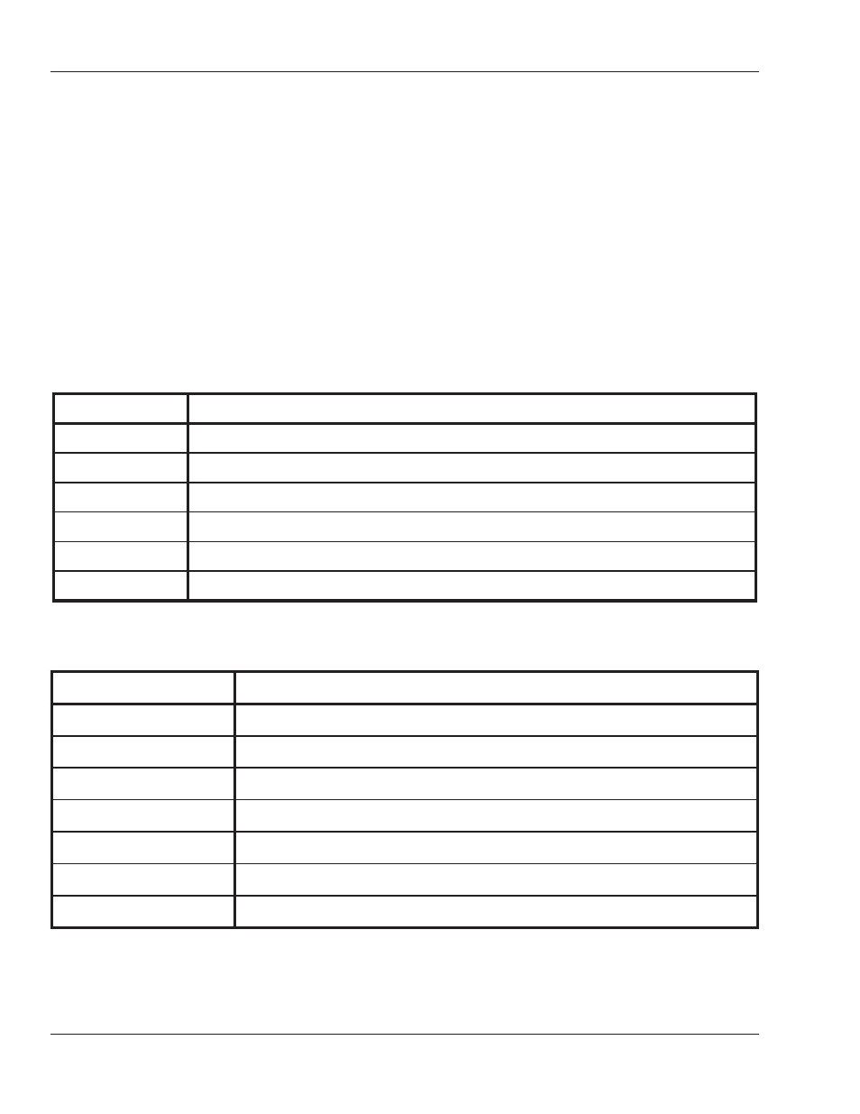
Table 2: TS-2 - Input Connections
Terminal
Connection
9
Request to Exit Input
10
Ground
11
Door Monitor Switch Input (NC Standby)
12
Auxiliary Input 1
13
Ground
14
Auxiliary Input 2
Table 3: TS-2 - Output Connections
Terminal
Connection
1
+5 VDC @ 400mA Max. Output for External Card Reader
2
Card Reader: Wiegand D0 or Magnetic Stripe Data Input
3
Card Reader: Wiegand D1 or Magnetic Stripe Clock Input
4
Ground
5
Lock Output or Wiegand D1 or Magnetic Stripe Clock Output
6
Auxiliary Output 0 or Wiegand Data 0 or Magnetic Stripe Data Output
7
Auxiliary Output 1zt