Installation and test, A. wiring – ACR&Artex C406-N User Manual
Page 88
ACR ELECTRONICS, INC / ARTEX PRODUCTS
DESCRIPTION, OPERATION, INSTALLATION AND MAINTENANCE MANUAL
C406-N (453-5060), C406-N HM (453-5061)
25-62-13
Page 88 of 109
MAR 1/13
TASK 25-62-13-450-801
2. Installation and Test
SUBTASK 25-62-13-450-001
A. Wiring
(1)
Coordinate installation of the PA with installation of the remote switch harness ELT plug. Refer
to SUBTASK 25-62-13-450-002 on page 72.
(2)
If the PA is undergoing installation on an aircraft with an existing ELT and remote switch
harness, perform the following procedure, otherwise proceed to Step (3):
(a)
Loosen the strain relief clamp and unscrew the strain relief from the plug body.
(b)
Remove the wiring from the ELT mating plug by extracting the contact sockets using
extraction tool MS27495R22MS, or equivalent.
(c)
Remove the jumper from Pin 3 and Pin 4.
(d)
Remove the sealing grommet plugs and empty contact sockets from Pin locations 1, 2,
15, and 16.
(3)
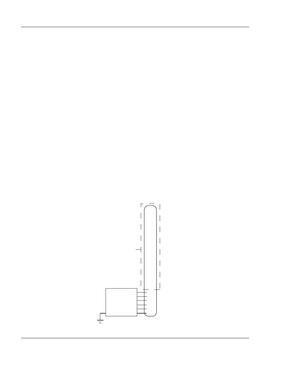
Loop the PA wires back through the wire path such that they exit at the front of the PA. See
"Figure 28. Programming Adapter”, on page 86.
(4)
Terminate the contact sockets of the six PA wires in the remote switch harness ELT plug using
insertion tool MS27495A22MS, or equivalent. See "Figure 29. Programming Adapter Interface
Figure 29. Programming Adapter Interface Wiring Diagram
6
7
9
8
12
13
19
20
22
10
21
3
4
1
2
15
16
14
11
18
17
5
ELT
PLUG
BLACK
ORANGE
RED
BROWN
GREEN
YELLOW
DGND
BDOUT
+5VDNGL
DDCS
BDIN
BDCLK
PROGRAMMING
ADAPTER
SEE FIGURE 21:
REMOTE SWITCH
HARNESS WIRING
DIAGRAM
NOTE: GROUND STRAIN RELIEF TO AIRFRAME
AS CLOSE TO ELT AS POSSIBLE.