Operation, A. operational overview, Figure 8. elt operational flow diagram – ACR&Artex C406-N User Manual
Page 33
25-62-13
Page 33 of 109
MAR 1/13
ACR ELECTRONICS, INC / ARTEX PRODUCTS
DESCRIPTION, OPERATION, INSTALLATION AND MAINTENANCE MANUAL
C406-N (453-5060), C406-N HM (453-5061)
TASK 25-62-13-870-803
2. Operation
SUBTASK 25-62-13-870-001
A. Operational Overview
(1)
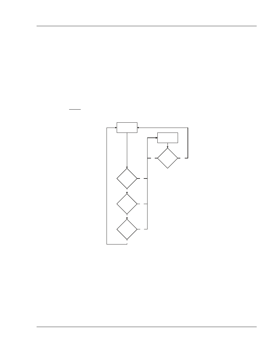
See "Figure 8. ELT Operational Flow Diagram".
(2)
A primary feature of the C406-N Series ELT is its simplicity of operation. As long as the ELT is
connected to the remote switch harness ELT connector, such that pins 12 and 13 are
jumpered (G-switch loop), it will activate in the event of a crash.
NOTE: Neither the cockpit remote switch or the ELT local switch can be positioned in such a
manner as to prevent automatic activation when the ELT is connected properly.
Figure 8. ELT Operational Flow Diagram
(3)
ELT operation is designed to prevent human error and misuse in regards to automatic
activation. The ELT cannot be activated by dropping, rough handling or during shipping.
(4)
When the ELT is activated, the presence of the emergency sweep tone and the flashing
cockpit remote switch panel LED indicates an active, normal functioning ELT. The remote
switch LED must immediately begin to flash continuously upon ELT activation.
ELT
“INACTIVE”
ELT “ACTIVE”
BUZZER “ON”
LED “ON”
ELT
SWITCH
“ON”
REMOTE
SWITCH
“ON”
G-SWITCH
“ON”
ELT OR
REMOTE SW
“RESET”
YES
YES
NO
NO
NO
YES
NO
YES