Figure 20. remote switch harness arrangement – ACR&Artex C406-N User Manual
Page 68
ACR ELECTRONICS, INC / ARTEX PRODUCTS
DESCRIPTION, OPERATION, INSTALLATION AND MAINTENANCE MANUAL
C406-N (453-5060), C406-N HM (453-5061)
25-62-13
Page 68 of 109
MAR 1/13
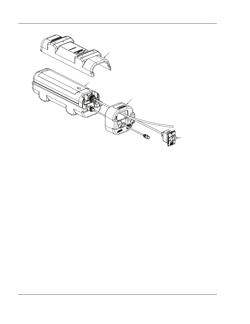
Figure 20. Remote Switch Harness Arrangement
(3)
Fabricate a shielded, twisted pair of sufficient length to reach from the harness ELT plug to
the aircraft navigation system ARINC 429 output.
(a)
Strip approximately 0.19 in. (5 mm) from the ELT ends.
(b)
Prepare the wire ends at the navigation system ARINC 429 output in accordance with
the manufacturer’s written instructions.
(c)
Dress and tin the bare wires to prevent the strands from fraying during terminal
crimping operations.
(4)
See "Figure 21. Remote Switch Harness Wiring Diagram”, on page 69.
TO ARINC 429 SOURCE
TO ANTENNA
REMOTE SWITCH
ELT
PROTECTIVE
TOP COVER
MOUNTING FRAME
CAP ASSEMBLY