C. orientation – ACR&Artex C406-N User Manual
Page 82
ACR ELECTRONICS, INC / ARTEX PRODUCTS
DESCRIPTION, OPERATION, INSTALLATION AND MAINTENANCE MANUAL
C406-N (453-5060), C406-N HM (453-5061)
25-62-13
Page 82 of 109
MAR 1/13
SUBTASK 25-62-13-410-001
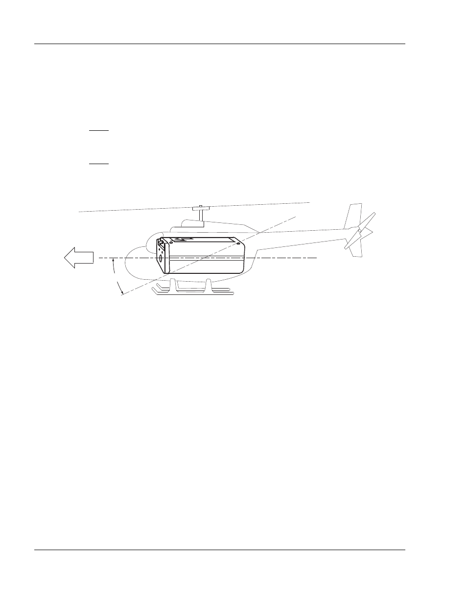
C. Orientation
(1)
Mount the C406-N HM ELT parallel to the waterline of the fuselage, along the longitudinal
axis, with the direction-of-flight arrow on the ELT pointing forward. See "Figure 27.
Orientation of ELT for Helicopter Installations".
NOTE: This is the orientation of the primary G-switch in the ELT.
(2)
The ELT may be angled downward as much as 25°, if necessary.
NOTE: Keep in mind, the steeper the mounting angle, the more pre-load on the primary G-
switch and the increased likelihood of “nuisance” activations.
(3)
All other installation requirements contained herein are applicable and must be adhered to.
Figure 27. Orientation of ELT for Helicopter Installations
0° TO 25°
FLIGHT