2 external backup power supply connector, 3 console port, 3 leds – ZyXEL Communications GS-2750 User Manual
Page 45
Chapter 3 Hardware Overview
GS-2750 User’s Guide
45
To connect the power to the Switch, insert the female end of power cord to the power
receptacle on the rear panel. Connect the other end of the supplied power cord to a power
outlet. Make sure that no objects obstruct the airflow of the fans.
The Switch’s AC unit requires a power supply of 100~240 VAC, 0.8 A.
3.2.2 External Backup Power Supply Connector
The Switch supports external backup power supply (BPS).
The Switch constantly monitors the status of the internal power supply. The backup power
supply automatically provides power to the Switch in the event of a power failure. Once the
Switch receives power from the backup power supply, it will not automatically switch back to
using the internal power supply even when the power is resumed.
3.2.3 Console Port
For local management, you can use a computer with terminal emulation software configured
to the following parameters:
• VT100 terminal emulation
• 9600 bps
• No parity, 8 data bits, 1 stop bit
• No flow control
Connect the male 9-pin end of the RS-232 console cable to the console port of the Switch.
Connect the female end to a serial port (COM1, COM2 or other COM port) of your computer.
3.3 LEDs
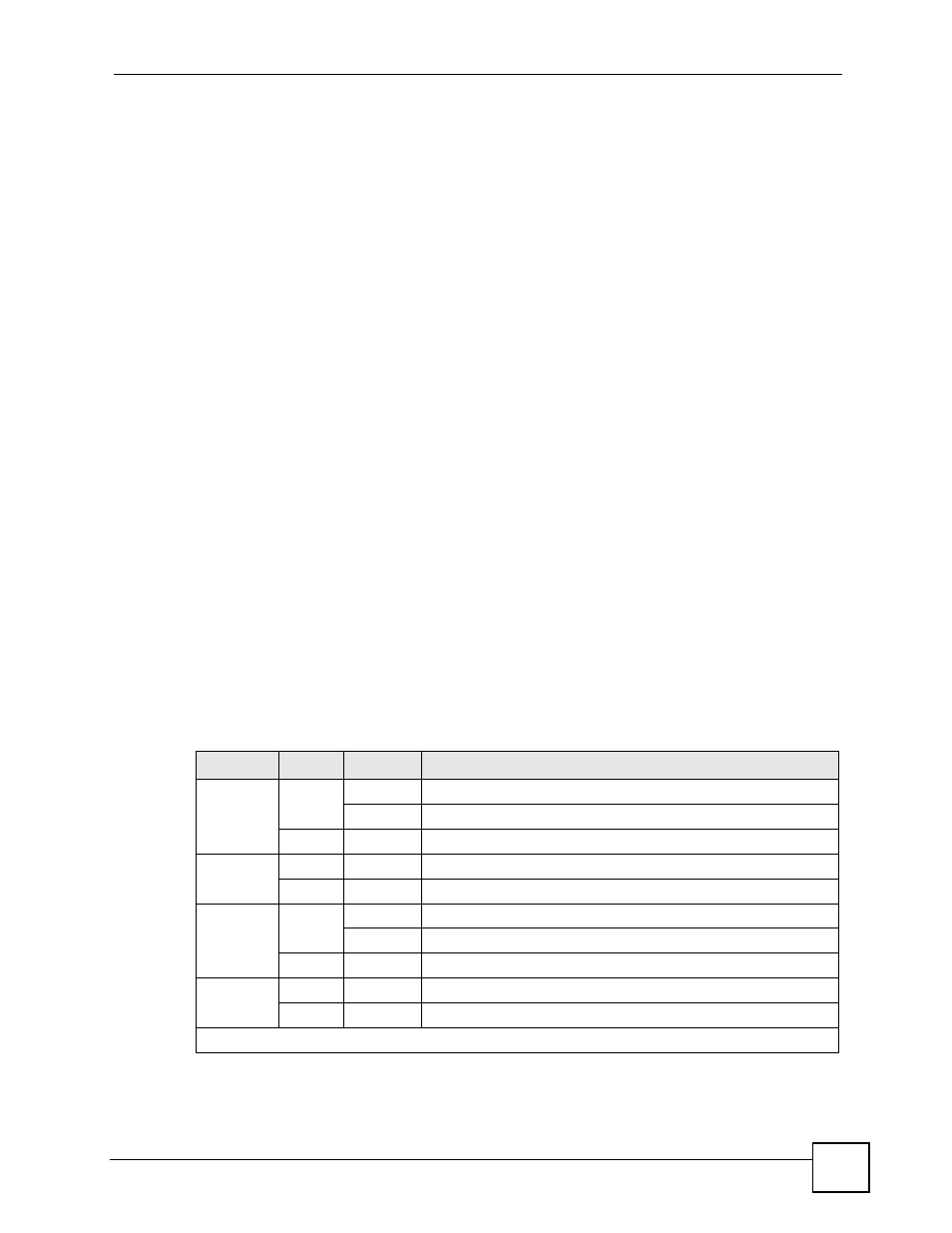
The following table describes the LEDs.
Table 3 LEDs
LED
COLOR STATUS
DESCRIPTION
BPS
Green
Blinking
The system is receiving power from the backup power supply.
On
The backup power supply is connected and active.
Off
The backup power supply is not ready or not active.
PWR
Green
On
The system is turned on.
Off
The system is off.
SYS
Green
Blinking
The system is rebooting and performing self-diagnostic tests.
On
The system is on and functioning properly.
Off
The power is off or the system is not ready/malfunctioning.
ALM
Red
On
There is a hardware failure.
Off
The system is functioning normally.
10/100/1000 Mbps RJ-45 Ethernet Ports