2 rear panel, 1 power connector – ZyXEL Communications GS-2750 User Manual
Page 44
Chapter 3 Hardware Overview
GS-2750 User’s Guide
44
Figure 12 Transceiver Removal Example
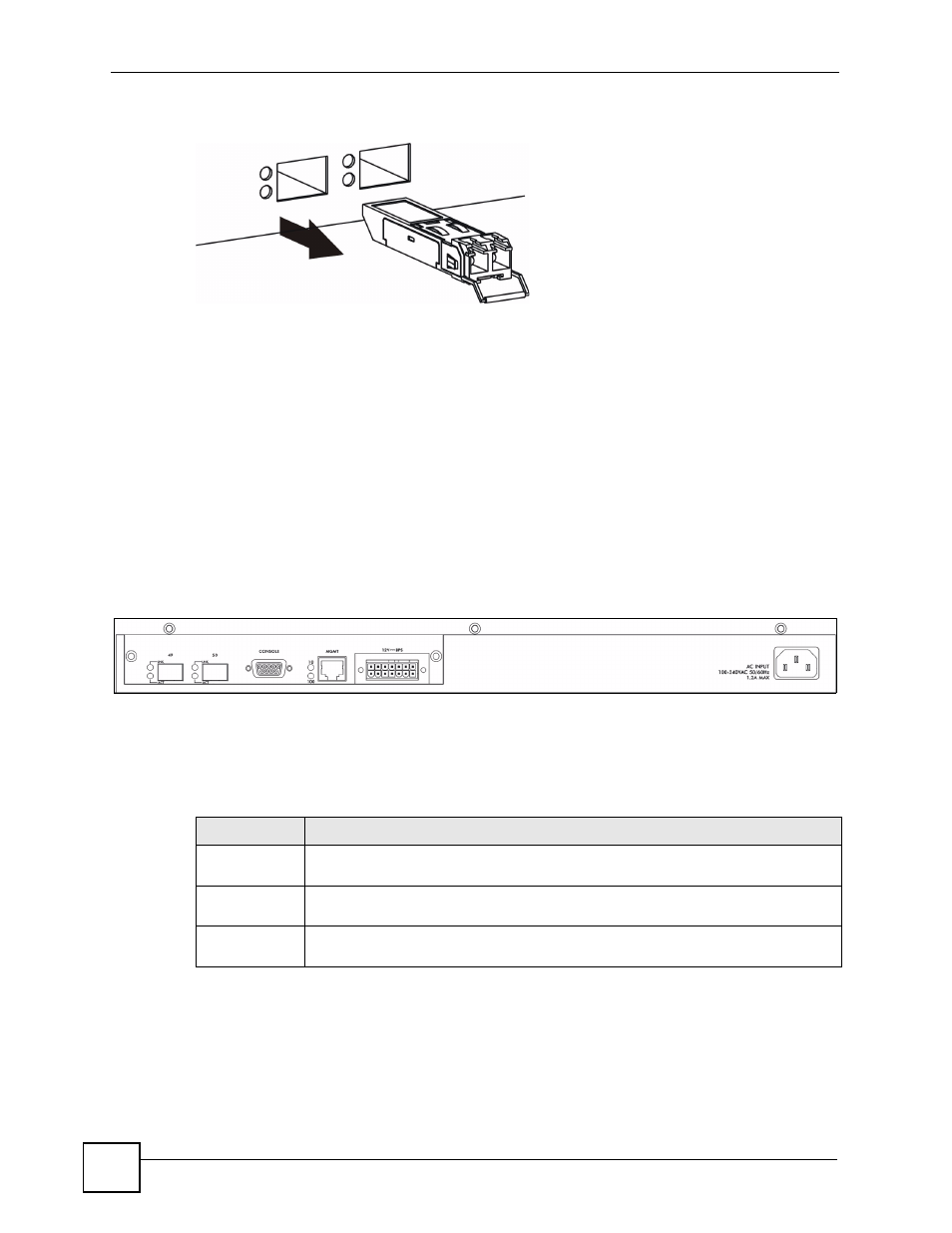
3.2 Rear Panel
The following figures show the rear panels of the AC and DC power input model switches.
The rear panels contain:
• Two Mini-GBIC uplink slots (A)
• An RS-232 management console port (B)
• An RJ-45 out-of-band management port (C)
• A connector for the backup power supply (D)
• A connector for the power receptacle (E)
Figure 13 Rear Panel - AC Model
The following table describes the ports on the rear panel.
3.2.1 Power Connector
Make sure you are using the correct power source as shown on the panel.
B
D
E
A
C
Table 2 Panel Connections
CONNECTOR
DESCRIPTION
2 Mini-GBIC
Slots
Use mini-GBIC transceivers in these slots for fiber-optic connections to backbone
Ethernet switches.
Console Port
Only connect this port to your computer (using an RS-232 cable) if you want to
configure the Switch using the command line interface (CLI) via the console port.
Management
Port
Connect to a computer using an RJ-45 Ethernet cable for local configuration of the
Switch.