Awa sns= dmx= sel= pos= awa ofs= rtmå dir, Vpha spd= wav= pos= vpha rtmå dir, Vib dpt= vol= sel= pos= vib rtmå dir – Zoom 8080 User Manual
Page 50: Oct -1l= -2l= pos= oct dry= rtmå dir, Effect types and parameters, Parameters comment values
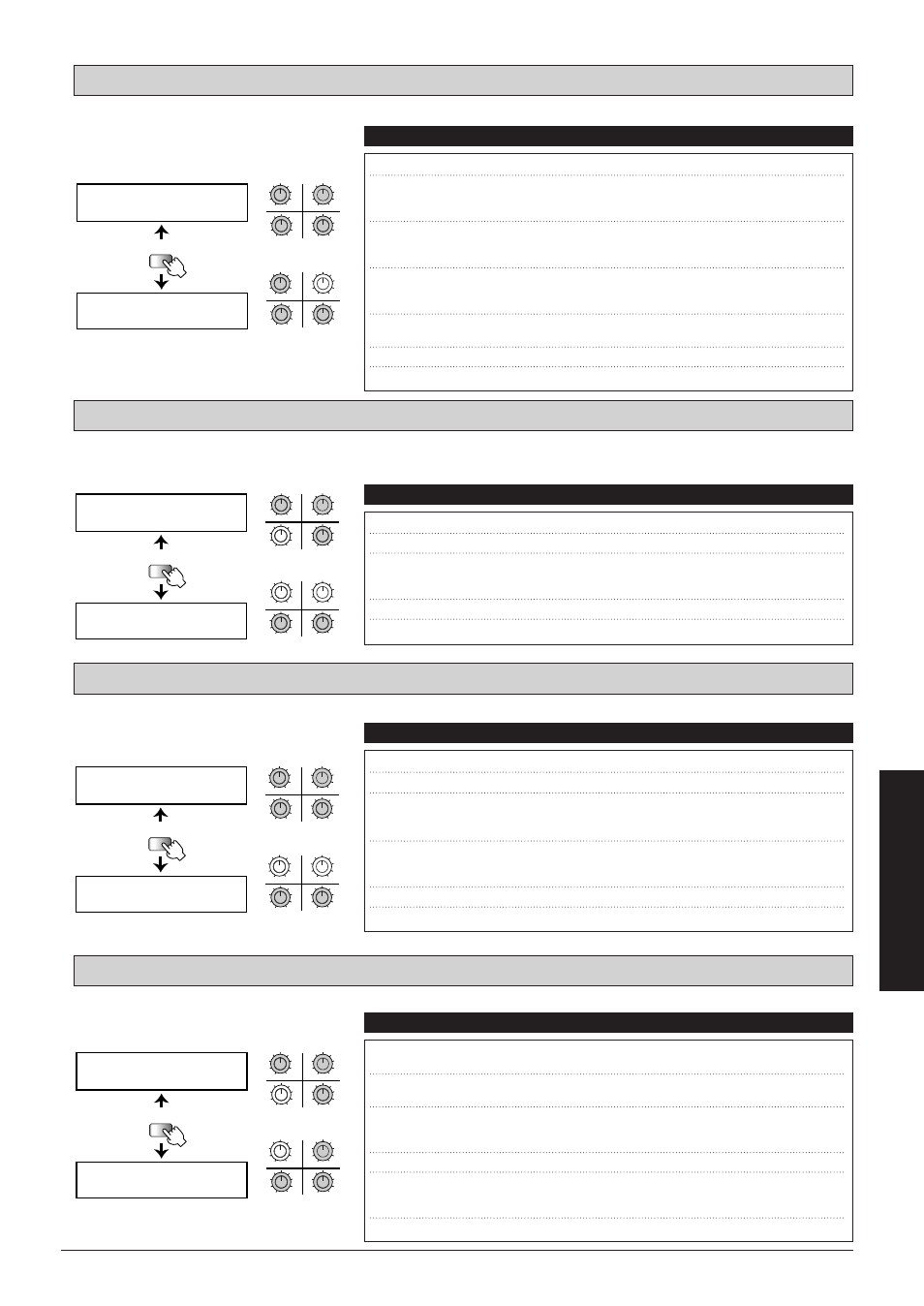
Standard auto-wah effect where wah depends on picking intensity.
Sound effect with a distinct undulation. Recreates a phaser type made popular by fusion guitarists in the seventies and
eighties.
Recreates a vintage-type vibe effect where the intensity and speed depends on the pedal action.
Adds a 1-octave or 2-octave lower component to the original sound.
OCT: Octaver
VIB: Vintage Vibe
VPHA: Vintage Phaser 1
AWA: Auto-Wah 2
49
■
Effect
Types
and
Parameters
UTILITY
PAGE
AWA SNS= DMx=
SEL= POS=
AWA OFS=
RTMå DIR=
3
4
1
2
MAX
MIN
MAX
MIN
MAX
MIN
MAX
MIN
q
w
e
r
3
4
1
2
MAX
MIN
MAX
MIN
MAX
MIN
MAX
MIN
y
u
t
PAGE 1
PAGE 2
q
w
e
r
y
u
t
q SNS (Sensitivity)
Sets the wah effect sensitivity.
1 – 50
w DRY (Dry Mix)
Sets the balance between effect sound and dry
sound (original sound).
When set to 0, no original sound is output.
0 – 10
e SEL (Type Select)
Sets the wah effect direction. When set to "up",
the center frequency is shifted upwards, and when
set to "dwn" downwards.
dwn, up
r POS (Insert Position) Sets the module insertion point. "BFR" means
before the DIST module and "AFT" after the
DIST module.
BFR, AFT
t OFS (Offset)
Sets the center frequency where the wah effect
becomes active.
Low, Hi
y RTM (RTM Destination) Shows which RTM parameter is being controlled.
SNS
u DIR (RTM Direction)
Sets the RTM direction.
NML, INV
Parameters
Comment
Values
UTILITY
PAGE
VPHA SPD= WAV=
POS=
VPHA
RTMå DIR=
3
4
1
2
MAX
MIN
MAX
MIN
MAX
MIN
MAX
MIN
q
w
e
3
4
1
2
MAX
MIN
MAX
MIN
MAX
MIN
MAX
MIN
r
t
PAGE 1
PAGE 2
q
w
e
r
t
q SPD (Speed)
Sets the undulation speed of the phaser effect.
1 – 50
w WAV (Wave Type)
Alters the undulation curve.
1 – 4
e POS (Insert Position) Sets the module insertion point. "BFR" means
before the DIST module and "AFT" after the
DIST module.
BFR, AFT
r RTM (RTM Destination) Shows which RTM parameter is being controlled.
SPD
t DIR (RTM Direction)
Sets the RTM direction.
NML, INV
Parameters
Comment
Values
UTILITY
PAGE
VIB DPT= VOL=
SEL= POS=
VIB
RTMå DIR=
3
4
1
2
MAX
MIN
MAX
MIN
MAX
MIN
MAX
MIN
q
e
w
r
3
4
1
2
MAX
MIN
MAX
MIN
MAX
MIN
MAX
MIN
t
y
PAGE 1
PAGE 2
q
w
r
e
t
y
q DPT (Depth)
Sets the depth of the vibe effect.
1 – 50
w VOL (Volume)
Sets the output level.
1 – 10
e SEL (Type Select)
"CHO" causes original sound to be mixed to the
effect sound to achieve a chorus effect.
"VIB" is the vibe sound only.
CHO, VIB
r POS (Insert Position) Sets the module insertion point. "BFR" means
before the DIST module and "AFT" after the
DIST module.
BFR, AFT
t RTM (RTM Destination) Shows which RTM parameter is being controlled.
SPD
y DIR (RTM Direction)
Sets the RTM direction.
NML, INV
Parameters
Comment
Values
UTILITY
PAGE
OCT -1L= -2L=
POS=
OCT DRY=
RTMå DIR=
3
4
1
2
MAX
MIN
MAX
MIN
MAX
MIN
MAX
MIN
q
w
e
r
3
4
1
2
MAX
MIN
MAX
MIN
MAX
MIN
MAX
MIN
t
y
PAGE 1
PAGE 2
q
w
r
e
t
y
q -1L (-1 Octave Level) Sets the output level of the 1-octave lower
component.
0 – 10
w -2L (-2 Octave Level) Sets the output level of the 2-octave lower
component.
0 – 10
e POS (Insert Position) Sets the module insertion point. "BFR" means
before the DIST module and "AFT" after the
DIST module.
BFR, AFT
r DRY (Dry Level)
Sets the original sound output level.
0 – 10
t RTM (RTM Destination) Shows the parameter that is being controlled by RTM.
The control range extends from "WLv" (Wet Level)
zero to the preset value set with "-1L" and "-2L".
WLv
y DIR (RTM Direction)
Sets the RTM direction.
NML, INV
Parameters
Comment
Values