Clearance requirements – Xantrex Technology GT3.0 User Manual
Page 46
Installation
2–18
975-0131-01-01
Clearance Requirements
For optimal and safe operation, ensure there is adequate clearance around the
inverter. The minimum clearance recommendations in Table 2-2 assume a vertical
mounting. If clearances are reduced below these minimums, rated power may not
be achieved.
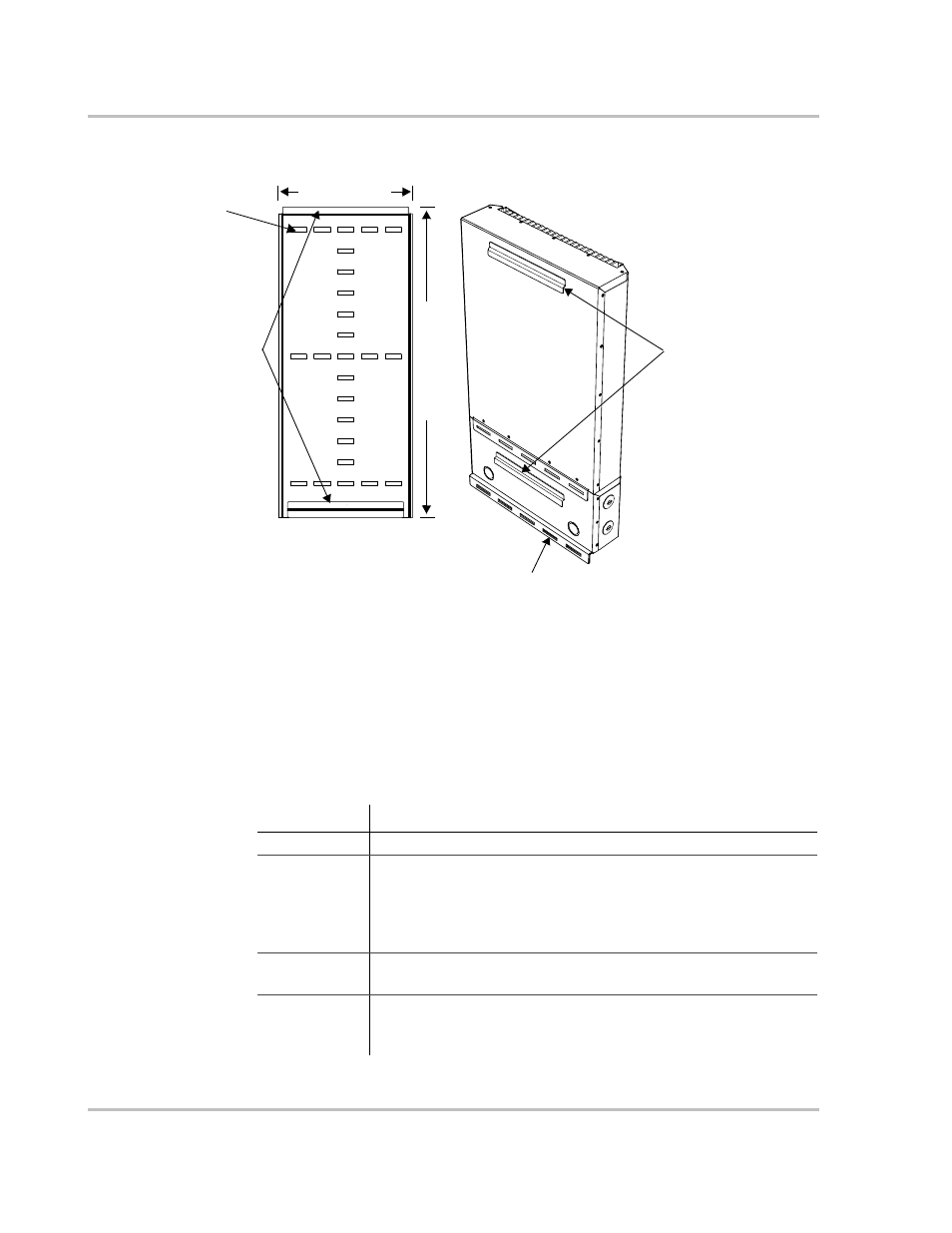
Figure 2-8 Mounting Bracket and GT Inverter
Mounting bracket
Back side of the inverter
Mounting slots for securing the inverter
Mounting flanges
Mounting flanges
Rectangular slots × 25:
8 mm × 30 mm
(5/16" × 1-3/16")
25.3 cm (10")
58.
7 cm
(
23.
1"
)
Table 2-2 Inverter Clearance Requirements
Location
Minimum Clearance
Above
30 cm (12 inches)
Below:
•
Inverter
•
Bracket
Outdoors:
•
100 cm (39 inches)
•
110 cm (43 inches)
Indoors: the same clearances are
recommended but not required.
The inverter extends below the
bracket by approximately 10 cm
(4 inches)
In front
Sufficient room to allow for easy access to read the display and to
prevent accidental contact with hot surface.
On sides
15 cm (6 inches) to prevent thermal derating. When mounting units
side by side, 30 cm (12 inches) of clearance between the two units is
recommended.