Accessing the belt control screen, Manipulating the top and bottom blowers, Viewing the status indicators – TurboChef Technologies 2020 User Manual
Page 34: From
1 8
O V E N M O D E S
Accessing the Belt Control Screen
From
TEST MODE
screen 1 (Figure 21, page 17),
press L2 to access the belt control screen (Figure
25). Use this mode to verify the belts work
correctly. The number after the belt speed
shows the pulses read by the HES. The
percentage is the amount of drive being asked
of the CMSC (100% = 10V).
To change the belt’s setting,
-Press L1 to turn the belts off.
-Press L2 to access the belt F controls.
-Press L3 to access the belt R controls.
Manipulating the Top and Bottom
Blowers
Figure 21, page 17.
The user can change the speed of the top and
bottom blowers independently. To change the
speed of the blowers,
1. From screen 1 of the
TEST MODE
, press R1
to access the top blower or R2 to access the
bottom blower.
2. Press the up or down keys to change the
speed of the selected blower in 5%
increments. The percentage of air cannot go
below 30% or above 100%.
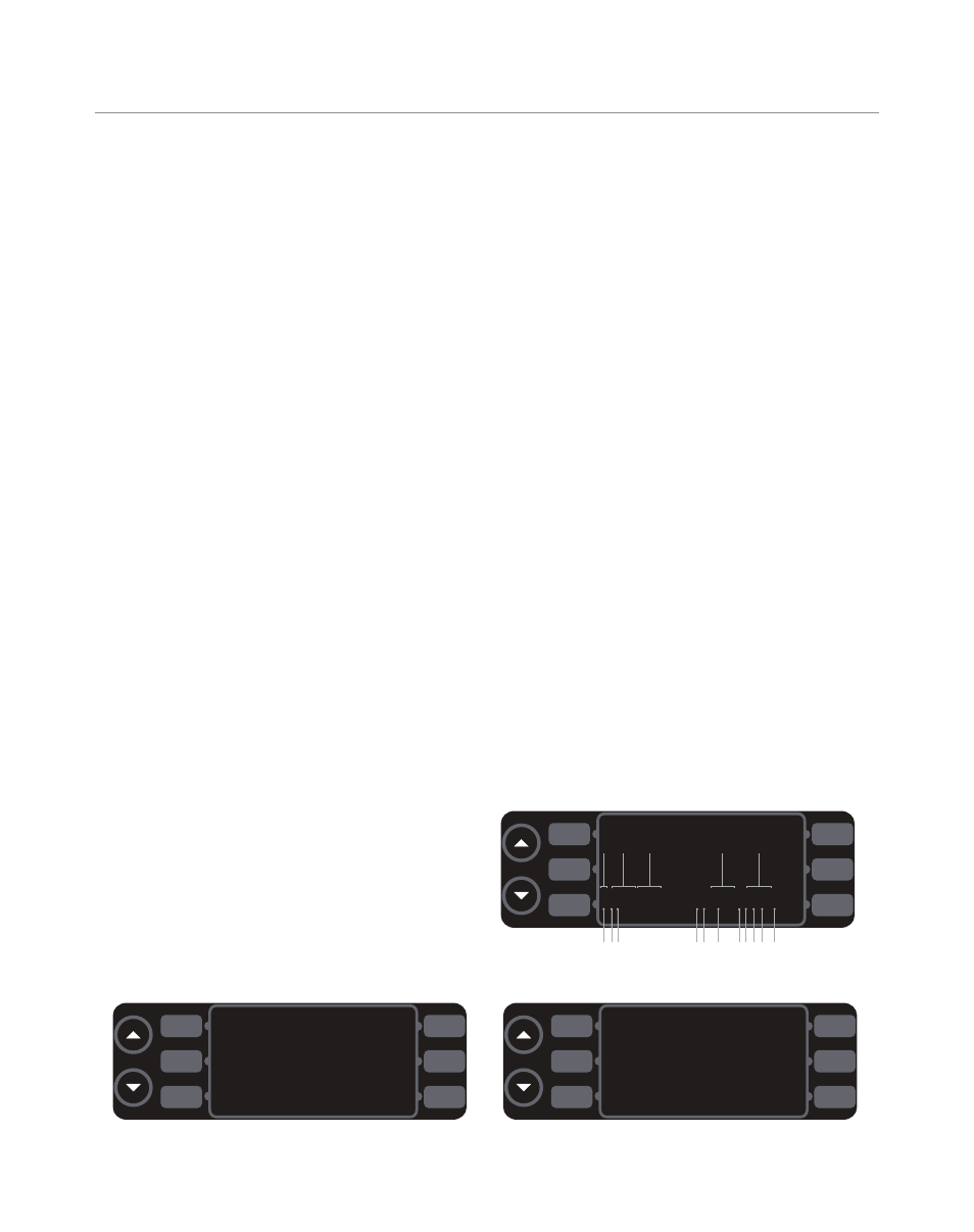
Viewing the Status Indicators
Figure 26
The status indicators are located at the bottom
of
TEST MODE
screen 1 and the heat control
screen. The status indicators are split into two
display lines.
Top Display Line
The top display line shows values relating to
oven components. The letters a-c and e below,
and on Figure 26, indicate the different top
display line status indicators, which are
explained below.
a
Shows which key is currently pressed.
-U = up key
-D = down key
-a = L1
-b = L2
-c = L3
-f = R1
-g = R2
-h = R3
-P = back/off key
-I = idle key
-S = emergency stop key
b
Shows the temperature within the electrical
compartment (temperature displayed in
Celsius only).
c
Shows the temperature within the cook
chamber.
d
Not applicable to this oven.
e
Shows the voltage of the power supply.
BELTS OFF
10:25 1920 36%
BELT F
BELT CTRL
BELT R
12:30 1343 31%
Figure 25: Belt Control Screen
L1
L2
L3
R1
R2
R3
D
EC27
100%
23.9V
450F
R
1
2
_
_
_
_
_
–
–
–
–
–
C
L
_
O
_
_
T
B
T
B
–
F
–
–
–
–
a
b
c
d
e
1 2 3
6
5
4
7 8 9 10 11
Figure 26: Status Indicator Explanation
INS
CANCEL
DEL
<---
--->
SAVE
[
]
Figure 27: Enter New Serial Number Screen
L1
L2
L3
R1
R2
R3
L1
L2
L3
R1
R2
R3