Understanding the parts of the projector – Toshiba TDP-MT500 User Manual
Page 12
12
PREPARING YOUR PROJECTOR
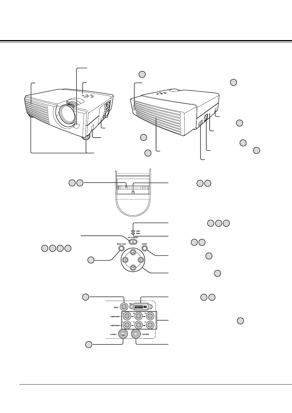
Understanding the parts of the projector
Focus ring:
Adjusts focus.
LAMP indicator
Directional button:
Used to shift menu item and adjust values.
ENTER button:
Used to determine menu item.
MENU/EXIT button:
Displays menu when pressed.
Erases menu when pressed again.
POWER button /
POWER indicator:
19
26
26
Operation panel
Remote control
photo-sensor (Front)
Angle adjusting
button
Terminal panel
Intake vent
15
Angle adjusting foot 15
14
26
33 36
19 23
19 23
TEMP (temperature)
indicator 33 36
23
34 36
33
17
18 22
17
17
Main power switch
I: Turn-on
O: Turn-off
Remote control photo-sensor (Rear)
Power cord inlet
Exhaust vent
Angle adjusting
button 15
33
18
14
VIDEO terminal:
Connects to such equipment as
video players with composite
video signals.
Zoom ring:
Expands projected picture images when
turned to the right (WIDE).
Contracts projected picture images
when turned to the left (TELE).
DVI terminal:
Connects to such equipment as video
equipment with DVI-D terminal and computers.
COMPONENT 1, 2 terminals:
Connects to such equipment as DVD players
with chrominance signals.
CONTROL terminal (Mini DIN 8P):
Used mainly for adjustments made by service
personnel.
S-VIDEO terminal:
Connects to such equipment as
video players with S-video
capability.
Operation panel (Top)
Terminal panel (Side)
Kensington Security
Lock Standard
connector