Toshiba RAV-SM560BT-E User Manual
Page 161
–
161
–
No.
Part name
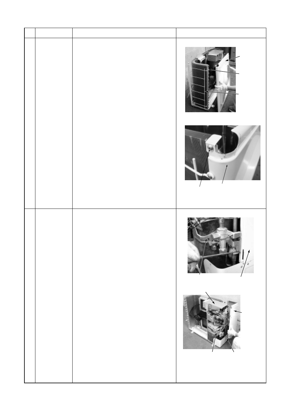
Discharge port
cabinet
Procedure
1. Detachment
1) Perform work of item 1 of
.
2) Take off screws (ST1T
Ø
4 x 10L, 3 pcs.) of
discharge port cabinet for the partition
plate.
3) Take off screws (ST1T
Ø
4 x 10L, 2 pcs.) of
discharge port cabinet for the bottom
plate.
4) Take off screw (ST1T
Ø
4 x 10L, 1 pc.) of
discharge port cabinet for the heat ex-
changer.
5) Take off screws (ST1T
Ø
4 x 10L, 2 pcs.) of
discharge port cabinet for the fin guard.
2. Attachment
1) Put the upper left side of the discharge
port cabinet on the end plate of the heat
exchanger, and then fix it with screw.
(ST1T
Ø
4 x 10L, 1 pc.)
2) Attach the removed screws to the original
positions.
Remarks
Side cabinet
1) Perform work of item 1 of
.
2) Remove screw fixing the inverter and the
side cabinet. (ST1T
Ø
4 x 10, 1 pc.)
3) Remove screws of the side cabinet and
the valve support plate.
(ST1T
Ø
4 x 10, 2 pcs.)
4) Remove screw of the side cabinet and the
cabling panel (Rear).
(ST1T
Ø
4 x 10, 1 pc.)
5) Remove screw of the side cabinet and the
bottom plate. (ST1T
Ø
4 x 10, 1 pc.)
6) Remove screw of the side cabinet and the
fin guard (Heat exchanger).
(ST1T
Ø
4 x 10, 2 pcs.)
Side cabinet
Inverter
Fin guard
End plate of the
heat exchanger
Discharge port
Valve support plate
Side cabinet
Inverter
Side cabinet
Cabling panel
(Rear)
Valve support
plate