Toshiba RAV-SM560BT-E User Manual
Page 110
–
110
–
2. Troubleshooting procedure
When a trouble occurred, check the parts along with the following procedure.
Trouble
→
→
→
→
→
Confirmation of check code by service mode
→
→
→
→
→
Check defective position and parts.
NOTE :
For cause of a trouble, power conditions or malfunction/erroneous diagnosis of microcomputer due to outer
noise is considered except the items to be checked. If there is any noise source, change the cable of the signal
line to shield cable.
(a) Outline of Judgment
A primary judgment to detect cause of error exists on the indoor unit or outdoor unit is performed in the
following procedure.
The indoor unit monitors operating status of the air conditioner, and if a protective circuit works, contents of
the self-diagnosis are displayed with a block restricted to the following cases on the indoor unit display part
(Sensors).
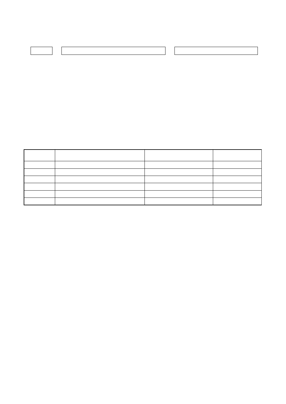
Remote
controller code
—
00
01
02
03
—
Block display
Operation lamp display flashes. (1Hz)
Operation lamp display flashes. (5Hz)
Operation/timer lamp displays flash. (5Hz)
Operation/defrost lamp displays flash. (5Hz)
Operation/timer/defrost lamp displays flash. (5Hz)
——
Contents of self-diagnosis
Power failure (In power ON)
Indoor P.C. board
Inter-unit cables/transmission system
Outdoor P.C. board
Cycle system, etc.
——
Check code
——
0b to 0F, 11, 12, b5, b6
04
14 to 19, 1A, 1C
1d, 1E, 1F, 21
1b, 8b
(b) Self-diagnosis by check code on the remote controller
In the wireless type models, the self-diagnosis for the protective circuit operation is performed by handling
the remote controller. First change the operation mode of the remote controller, and then perform the self-
diagnosis by the displayed contents of the remote controller and the existence of operation lamp flashing
(5Hz) and buzzer sound (Pi, Pi, Pi). During self-diagnosis operation, the timer lamp usually flashes (5Hz).
Selection of remote controller operation mode
1) Selection of service mode
Push the select button at lower side of the wireless remote controller with a tip of pencil, etc. for
approx. 3 seconds or more. In this time, check that [00] is displayed on the room temp. display part
and other displays go off.
2) Selection of normal mode
Push the reset button at lower side of the wireless remote controller with a tip of pencil, etc. In this
time, check that [
“
AM
”
] display on the time display part flashes.
Cautions in service
1) After service work, be sure to push the reset button to return the mode to normal mode.
2) After service by the check codes, turn off the power switch once and then turn on the switch to return
the stored memory in microcomputer to the initial status.