Connecting the h9 asd, Power connections, Figure 2 on pg. 16 – Toshiba H9 User Manual
Page 24: Danger
16
H9 ASD Installation and Operation Manual
Connecting the H9 ASD
Refer to the section titled
Installation Precautions on pg. 4
before attempting to connect the H9 ASD and the motor to electrical power.
Power Connections
Contact with the 3-phase input or output terminals may cause an electrical shock
resulting in injury or loss of life.
See
for a system I/O connectivity schematic.
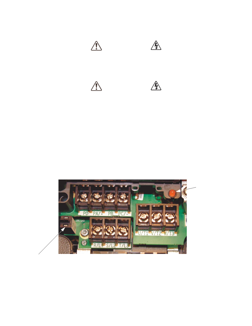
An inductor (DCL) may be connected across the PO and PA/+ terminals to provide additional filtering.
When not used, a jumper must be connected across these terminals (see
).
PA/+ and PB are used for the DBR connection if using a braking resistor.
PC/- is the negative terminal of the DC bus.
R/L1, S/L2, and T/L3 are the 3-phase input supply terminals for the H9 ASD.
U/T1, V/T2, and W/T3 are the output terminals of the H9 ASD that connect to the motor.
The location of the Charge LED for the smaller typeform ASD is provided in
. The Charge
LED is located on the front door of the enclosure of the larger ASDs.
Figure 2. Typical H9 ASD input/output terminals and the
DANGER
DANGER
Charge LED
Grounding Capacitor Switch — Pull for Small capacitance/Push for Large capacitance.