Sw6, sw7, sw8 - link modes, 2) set-up module and connect cables – Omnitron Systems Technology iConverter Gx AN Standalone Module User Manual
Page 2
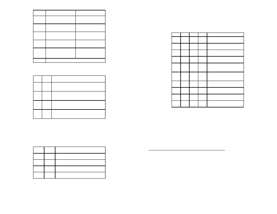
SW6, SW7, SW8 - Link Modes
These three DIP-switches configure the link mode settings. DIP-switch SW6 is valid
when Port 1 is set to “AN” or “MAN”. DIP-switches SW7 and SW8 are ignored when
Port 1 is set to “AN”. The following table details possible Link Mode DIP-switch
configurations.
SW1
SW6
SW7
SW8
Result
Down
(AN)
Down
Down
Down
Enables Link Segment mode (LS).
Down
(AN)
Up
Down
Down
Enables Link Propagate mode (LP).
Up
(MAN)
Down
Down
Down
Enables Link Segment mode (LS).
Up
(MAN)
Up
Down
Down
Enables Link Propagate mode (LP).
Up
(MAN)
Down
Up
Down
Enables Remote Fault Detection
mode plus Link Segment mode
(RFD+LS).
Up
(MAN)
Up
Up
Down
Enables Remote Fault Detection
mode plus Link Propagation mode
(RFD+LP).
Up
(MAN)
Down
Down
Up
Enables Symmetrical Fault Detect
mode (SFD).
Up
(MAN)
Up
Down
Up
Illegal Setting, Link Segment (LS) is
selected.
Up
(MAN)
Down
Up
Up
llegal Setting, Link Segment (LS) is
selected.
Up
(MAN)
Up
Up
Up
llegal Setting, Link Segment (LS) is
selected.
Figure E: Link Mode Table
NOTE: Connecting two converters set to any of the RFD modes is illegal and will
cause a “deadly embrace” lockup.
NOTE: It is recommended to keep the LS setting (default) until initial configuration
is complete.
For detailed information on the operation of the different Link Modes, download the
application note “
iConverter
Link Modes” available on Omnitron’s web page:
http://www.omnitron-systems.com/downloads.php
2) SET-UP MODULE AND CONNECT CABLES
a. The Gx AN is available in tabletop and wall-mounting models. For wall-mounting,
attach the unit to a wall, backboard or other flat surfaces. For tabletop installations,
place the unit on a flat level surface. Attach the rubber feet to the bottom of the unit
to prevent the unit from sliding. Make sure the unit is placed in a safe, dry and
secure location.
To power the unit using the AC/DC adapter, connect the AC/DC adapter to the AC
outlet. Then connect the barrel plug at the end of the wire on the AC/DC adapter to
the 2.5mm DC barrel connector (center-positive) on the chassis. Confirm that the
unit has powered up properly by checking the power status LED located on the
front of the unit.
To power the unit using a DC power source, prepare a power cable using a two-
conductor insulated wire (not supplied) with a 14 AWG gauge minimum. Cut the
power cable to the length required. Strip approximately 3/8 of an inch of insulation
Switch
Down
(Factory Default)
Up
SW1
P1 AN:
Port 1
Fiber Auto-Negotiation
P1 MAN:
Port 1
Fiber Manual Negotiation
SW2
P2 AN:
Port 2
UTP Auto-Negotiation
P2 MAN:
Port 2
UTP Manual
SW3
FDX:
Port 2
UTP Full-Duplex
HDX:
Port 2
UTP Half-Duplex
SW4
OFF:
Port 2
Pause Advertisement Enable
PAUSE:
Port 2
Pause Disable
SW5
OFF:
Port 2
Asymmetric Pause
Advertised
ASYM:
Port 2
Asymmetric Pause Not
Advertised
SW6 - SW8
See Link Mode Table
Figure B: DIP-Switches
SW2
SW3
Port 2 (UTP) Modes of Operation
AN
FDX
Configured for Auto-Negotiation.
It advertises and negotiates in this order:
1000FDX, 1000HDX
AN
HDX
Configured for Auto-Negotiation.
It advertises and negotiates:
1000HDX
MAN
FDX
Configured for Forced-Negotiation.
It advertises and negotiates:
1000FDX
MAN
HDX
Configured for Forced-Negotiation.
It advertises and negotiates:
1000HDX
Figure C: Port 2 (UTP) Modes
SW4 and SW5 - Port 2 Pause Advertisement “OFF PAUSE” “OFF ASYM”
These DIP-switches are only valid when Port 1 is set to “MAN”. The PAUSE modes will
be based on the configuration of DIP-switches SW4 and SW5.
SW4
SW5
Port 2 (UTP) PAUSE Modes
OFF
OFF
No Pause advertised
OFF
ASYM
Asymmetric PAUSE towards link partner
PAUSE
OFF
Symmetric PAUSE
PAUSE
ASYM
Both Symmetric PAUSE and Asymmetric PAUSE
toward local device
Figure D: Pause Modes