To 24, Audio connection formats – Onkyo PR-SC5508 User Manual
Page 24
24
En
■
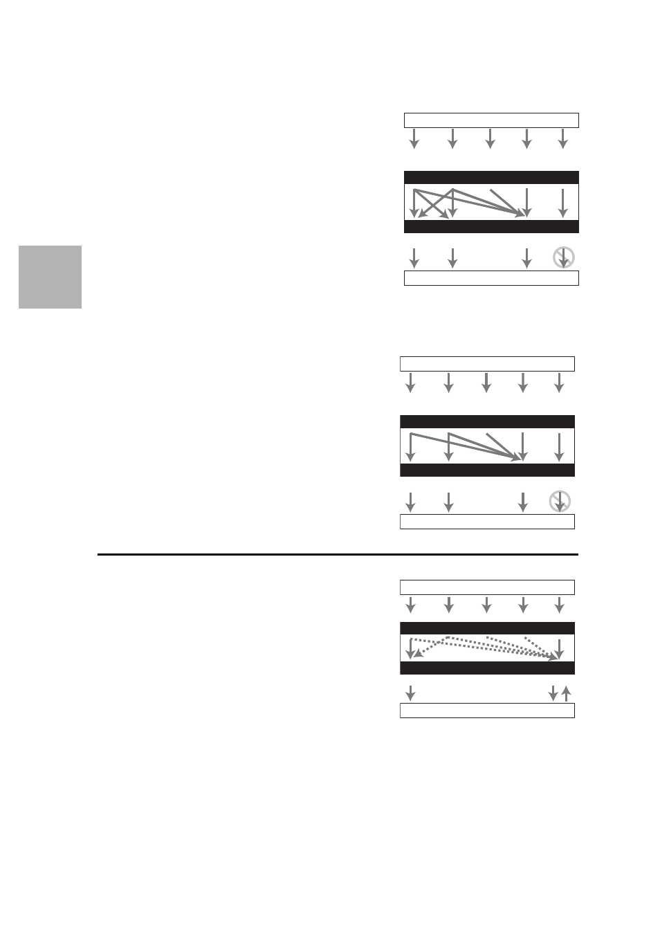
“Monitor Out” setting set to “Analog”
Video input signals flow through the AV controller as
shown, with composite video, S-Video and PC IN (Analog
RGB) sources being upconverted for the component video
output. Use this setting if you connect the AV control-
ler’s
COMPONENT VIDEO MONITOR OUT to your
TV.
Composite video is upconverted to S-Video and S-Video
is downconverted to composite video. Note that these con-
versions only apply to the MONITOR OUT V and S out-
puts, not the VCR/DVR OUT V and S outputs.
The composite video, S-Video and component video out-
puts pass through their respective input signals as they are.
This signal flow also applies when the “Resolution” set-
ting is set to “Through” (
45).
Video Signal Flow and the Resolution Setting
When the “Monitor Out” setting is set to “Analog”
(
44), if the “Resolution” setting is set to anything
other than “Through” (
45), the video signal flow will
be as shown here, with composite video, PC IN (Analog
RGB) and S-Video sources being upconverted for the
component video output.
The composite video, S-Video and component video
outputs pass through their respective analog input sig-
nals as they are. HDMI input signals are not output.
Audio Connection Formats
Audio component can be connected by using any of the
following audio connection formats: analog, analog multi-
channel, optical, coaxial, or HDMI.
When choosing a connection format, bear in mind that the
AV controller does not convert digital input signals for
analog line outputs and vice versa. For example, audio sig-
nals connected to an optical or coaxial digital input are not
output by the analog VCR/DVR OUT.
If signals are present at more than one input, the inputs
will be selected automatically in the following order of pri-
ority: HDMI, digital, analog.
IN
MONITOR OUT
*
1
Blu-ray Disc/DVD player, etc.
AV controller
TV, projector, etc.
Composite
Composite
S-Video
Component
Video Signal Flow Chart
HDMI
HDMI
*1
For details, refer to “Video Resolution
Chart” (
S-Video
Component
PC IN
(Analog RGB)
IN
MONITOR OUT
AV controller
TV, projector, etc.
Blu-ray Disc/DVD player, etc.
Composite
Composite
S-Video
Component
Video Signal Flow Chart
HDMI
HDMI
S-Video
Component
PC IN
(Analog RGB)
IN
OUT
*
1
*
2
*
1
*
1
*
1
*
3
*
1
*
3
Blu-ray Disc/DVD player, etc.
AV controller
TV, projector, etc.
HDMI
Coaxial
Analog
Audio Signal Flow Chart
HDMI
Analog
Multichannel
*1
Depends on the “Audio TV Out” setting (
*2
This setting is available, when “Audio Return Channel”
setting is set to “Auto” (
61), you must select the TV/CD
input selector and your TV must support ARC function.
*3
Only the front L/R channels are output.
Optical