Emissivity setting (analog controlled), 1 emissivity setting (analog controlled), Installation – RayTek 54301 User Manual
Page 32: 24 mid
Installation
5.4.1 Emissivity Setting (analog controlled)
The input FTC1 can be configured to accept an analog voltage signal
(0 to 5 VDC) to provide real time emissivity setting. The following
table shows the relationship between input voltage and emissivity.
U in V
0.0 0.5 … 4.5 5.0
Emissivity
0.1 0.2 … 1.0 1.1
Table 4: Ratio between Analog Input Voltage and Emissivity
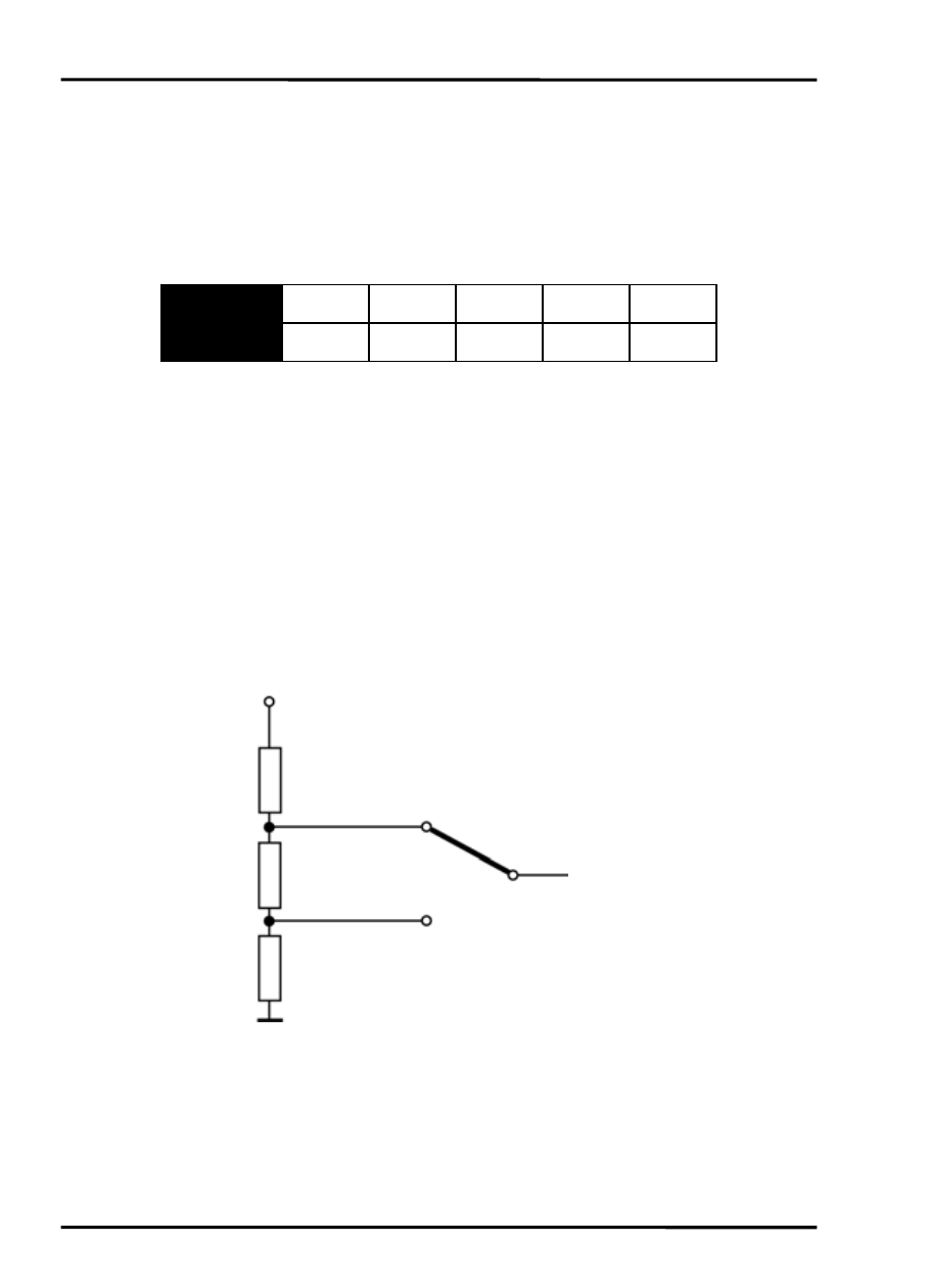
Example:
The process requires the setting of emissivity:
• for product 1: 0.90
• for product 2: 0.40
Following the scheme below, the operator needs only to switch to
position “product 1” or “product 2”.
+ 5 VDC
“product 1”
R1 = 200 Ω
4.0 V (ε=0.9)
To the input FTC1
of the sensor
R2 = 500 Ω
1.5 V (ε=0.4)
“product 2”
R3 = 300 Ω
Figure 14: Adjustment of Emissivity at Input FTC1 (Example)
24
MID