Oscillator sources, Reset circuit – Renesas SH2/7137 User Manual
Page 22
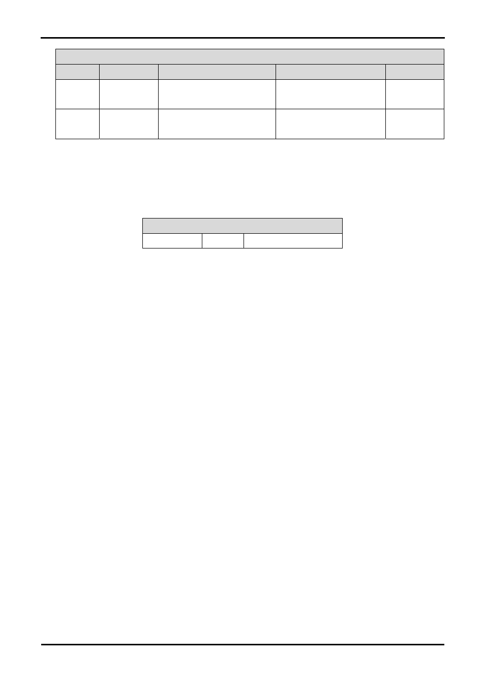
Option Link Settings
Reference
Function
Fitted
Alternative (Removed)
Related To
R46 Switches
configuration
SW3 can be used for ADTRGn
SW3 can not be used for
ADTRGn
R48
R48 Switches
configuration
SW3 can be used for IRQ2
SW3 can not be used for IRQ2
R46
Table 6-14: Switches configuration links.
6.8. Oscillator Sources
A crystal oscillator is fitted on the RSK and used to supply the main clock input to the Renesas microcontroller. Table 6-15 details the
oscillators that are fitted and alternative footprints provided on this RSK:
Component
Crystal (X1)
Fitted
10 MHz (HC49/4H package)
Table 6-15: Oscillators / Resonators
6.9. Reset Circuit
The CPU Board includes a simple latch circuit that links the mode selection and reset circuit. This provides an easy method for swapping
the device between Boot Mode and User mode. This circuit is not required on customer’s boards as it is intended for providing easy
evaluation of the operating modes of the device on the RSK. Please refer to the hardware manual for more information on the
requirements of the reset circuit.
The Reset circuit operates by latching the state of the boot switch on pressing the reset button. This control is subsequently used to
modify the mode pin states as required.
The mode pins should change state only while the reset signal is active to avoid possible device damage.
The reset is held in the active state for a fixed period via a resistor/capacitor delay circuit. Please check the reset requirements carefully
to ensure the reset circuit on the user’s board meets all the reset timing requirements.
20