Renesas SH2/7137 User Manual
Page 20
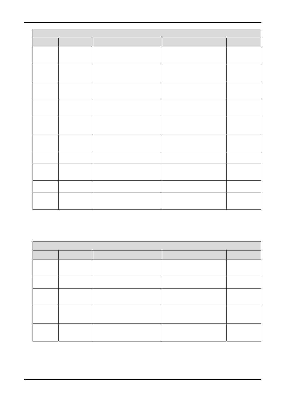
Option Link Settings
Reference
Function
Fitted
Alternative (Removed)
Related To
R33 MCU
power
supply
Supply to MCU.
CPU current can be measured
across R33
R161 Ground Connects Analog & Digital
grounds together.
Separates Analog & Digital
grounds.
R23 Power
source
5V source signal will be powered
from E8A_VCC.
5V source signal will not be
powered from E8A_VCC.
R3, R10, R24
R24 Power
source
CON_5V source signal will be
powered from E8A_VCC.
CON_5V source signal will not be
powered from E8A_VCC.
R3, R10, R23
R10 Power
source
E8A_VCC will be used as external
source.
E8A_VCC will not be used as
external source.
R3, R10, R23
R3 Power
source
Enables external power to board
from PWR connector.
Disable external power to board
from PWR connector.
R10, R23, R24
R29 Power
source
Board_VCC = 5V (or J5 1-2)
Board_VCC = 3V3 (or J5 2-3)
R24, R35
R24
Power source
CON_3V3 source signal will be
powered from E8A_VCC.
CON_3V3 source signal will not
be powered from E8A_VCC.
R29, R35
R35
Power source
Board_VCC = 3V3 (or J5 2-3)
Board_VCC = 5V (or J5 1-2)
R24, R29
R40 Power
source
Board_VCC source signal will be
powered from E8A_VCC.
Board_VCC source signal will not
be powered from E8A_VCC.
Table 6-9: Power configuration links.
Table 6-10 below describes the function of the option links associated with clock configuration. The default configuration is indicated by
BOLD text.
Option Link Settings
Reference
Function
Fitted
Alternative (Removed)
Related To
R123 Clock
Oscillator
External Clock Source
On-board Clock Source
R126, R135,
R138
R130
Clock Oscillator
Parallel resistor for a crystal
Not fitted
R138 Clock
Oscillator
External Clock Source
On-board Clock Source
R123, R126,
R135
R135 Clock
Oscillator
On-board clock source is used
External clock source is used
R123, R126,
R138
R126 Clock
Oscillator
On-board clock source is used
External clock source is used
R123, R135,
R138
Table 6-10: Clock configuration links.
Table 6-11 below describes the function of the option links associated with reference voltage source. The default configuration is indicated
by BOLD text.
18