Rcan-et, Debug lcd module, Table 6-3 – Renesas SH2/7137 User Manual
Page 12
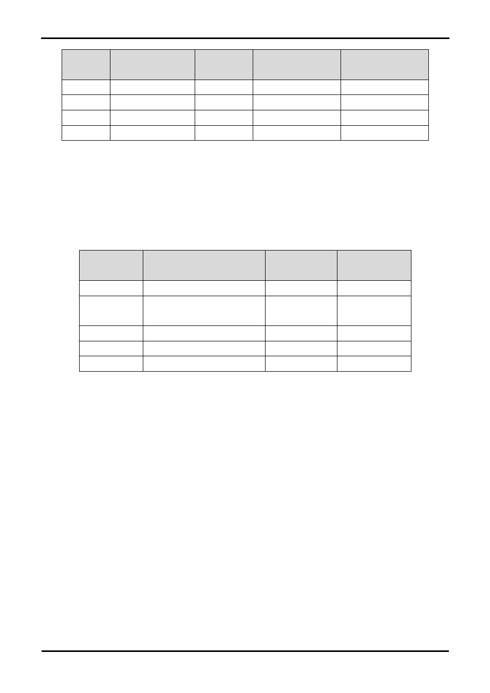
Description
Function
Microcontroller
Port Pin
Fit for RS232
Remove for RS232
SCI2
Default serial port
58
R30
R53
SCI2
Default serial port
60
R39
R54
SCI0
Spare Serial Port
68
R53
R30
SCI0
Spare Serial Port
69
R54
R39
Table 6-3: Serial Port settings
The SCI2 port is also available on J3 and JA6. The SCI0 port is available on J3 and JA2.
6.5. RCAN-ET
The RCAN module can be used for RCAN communication.
Table 6-4 contains details of the signal descriptions and pin connections.
Description
Function
Microcontroller Pin
Number
Header Pins
CTx0
Transmit data input
42
J2-12
CRx0
Receive data output; reads out data
from the bus lines
41 J2-11
CAN_EN
Enable control input
49
J2-19
CAN_ERRn
Error and power-on indication output
63
J3-13
CAN_STBn
Standby control input
43
J2-13
Table 6-4: CAN module settings
6.6. Debug LCD Module
A debug LCD module is supplied to be connected to the connector LCD. This should be fitted so that the debug LCD module lies over J3.
Care should be taken to ensure the pins are inserted correctly into LCD. The debug LCD module uses a 4 bit interface to reduce the pin
allocation. No contrast control is provided; this is set by a resistor on the supplied display module. The module supplied with the RSK only
supports 5V operation.
Table 6-5 shows the pin allocation and signal names used on this connector.
10