Family e10a-usb emulator user’s manual – Renesas Emulator System SH7362 User Manual
Page 21
13
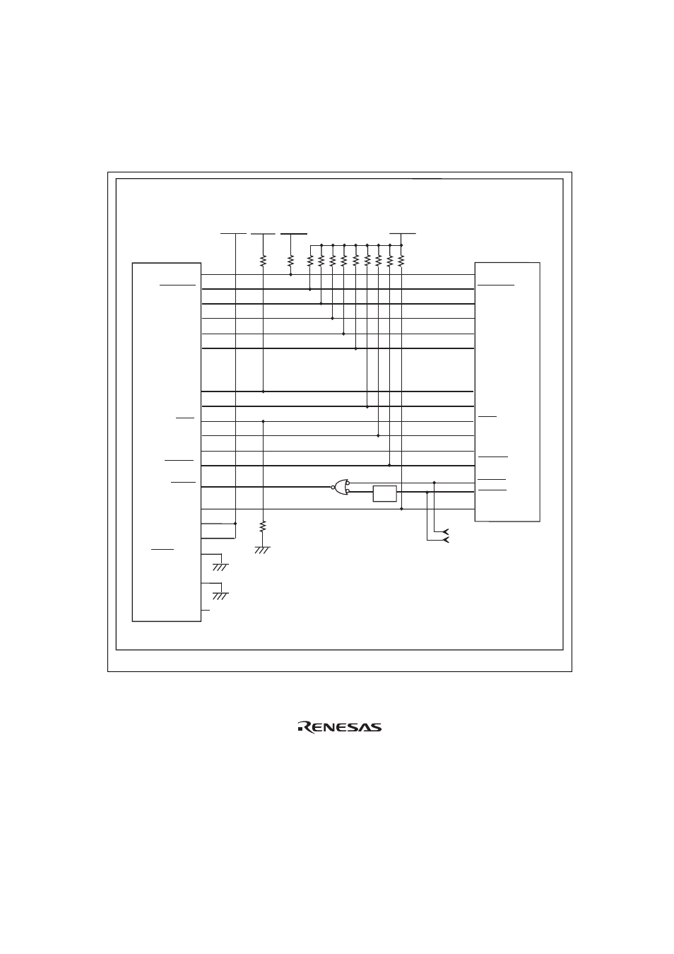
When the circuit is connected as shown in figure 1.7, the switches of the emulator are set as SW2
= 1 and SW3 = 1. For details, refer to section 3.8, Setting the DIP Switches, in the SuperH
TM
Family E10A-USB Emulator User’s Manual.
SH7362
6
AUDATA0
AUDATA2
AUDATA1
AUDATA3
TCK
TMS
TDI
TDO
UVCC
UVCC_AUD
MPMD(GND)
32
30
28
26
24
15
17
21
19
11
8
9
3
14
12
5
AUDATA0
AUDATA2
AUDATA1
AUDATA3
TCK
TMS
TDO
TDI
AUDCK
AUDCK
N.C.
MPMD
GND
1, 2, 4, 7,
10, 13, 16, 18,
20, 22, 23, 25, 27, 29,
31, 33, 34, 35, 36, 37, 38
GND bus leads
All pulled-up at 4.7 k
Ω
or more
User system
1 k
Ω
H-UDI port connector
(38-pin type)
VccQ_SR = 2.85-V/1.8-V I/O power supply
VccQ_MFI = 2.85-V/1.8-V I/O power supply
VccQ = 2.85-V I/O power supply
VccQ_SR
VccQ_SR
VccQ_SR
VccQ_SR
AUDSYNC
RESET
TRST
ASEBRK
/ BRKACK
RESETP
TRST
ASEBRK
/BRKACK
AUDSYNC
RESETA
*1
UCON (GND)
Reset signal
Power-on reset signal
*2
Level-shift
circuit
*3
Figure 1.7 Recommended Circuit for Connection between the H-UDI Port Connector and
MPU when the Emulator is in Use (38-Pin Type)
- Single-Chip Microcomputer M34551T2-MCU (42 pages)
- M3T-FLX-80NRA (6 pages)
- 70 (162 pages)
- M16C/30P (102 pages)
- PROM Programming Adapter PCA7427G02 (20 pages)
- R0E572110CFK00 (40 pages)
- H8/325 Series (20 pages)
- Single-Chip Microcomputer H8/36079 (27 pages)
- Direct Dummy IC M3T-DIRECT100S (4 pages)
- M3A-2152 (95 pages)
- PCA7755D (6 pages)
- M16C/6N5 (106 pages)
- SH7085 (50 pages)
- QFP-144 (23 pages)
- H8/3834 Series (22 pages)
- RSKM16C62P (3 pages)
- H8/33937 (22 pages)
- Single-Chip Microcomputer H8SX/1622 (5 pages)
- E6000 (29 pages)
- PCA7400 (18 pages)
- PCA4738FF-64 (20 pages)
- SuperH HS7339KCU01HE (43 pages)
- M16C FAMILY (103 pages)
- PCA7412F-100 (20 pages)
- 4513 (210 pages)
- M34551E8FP (16 pages)
- Dummy IC M3T-SSOP36B-450 (4 pages)
- Emulation Pod M30100T3-RPD-E (52 pages)
- Converter Board for M30102 M30102T-PTC (4 pages)
- SH7145 (31 pages)
- HS1653ECN61H (36 pages)
- Converter Board R0E521276CFG00 (4 pages)
- PCA7302E1F-80 (18 pages)
- H8/3814 Series (21 pages)
- H8S/2646 Series (20 pages)
- SuperHTM Family SH7125 Series (40 pages)
- M30262T-PTC (4 pages)
- SH7670 (82 pages)
- H8/3864 Series (20 pages)
- Emulator System M3T-MR100 (306 pages)
- 38K0 (6 pages)
- PLQP0176KB-A (40 pages)
- Direct Dummy IC M3T-DIRECT80S (6 pages)
- PCA4738L-80A (26 pages)
- Converter Board R0E5212BACFG00 (6 pages)