Renesas Emulator System SH7362 User Manual
Page 13
5
1. Input to or output from the user system.
2. The symbol (/) means that the signal is active-low.
Notes:
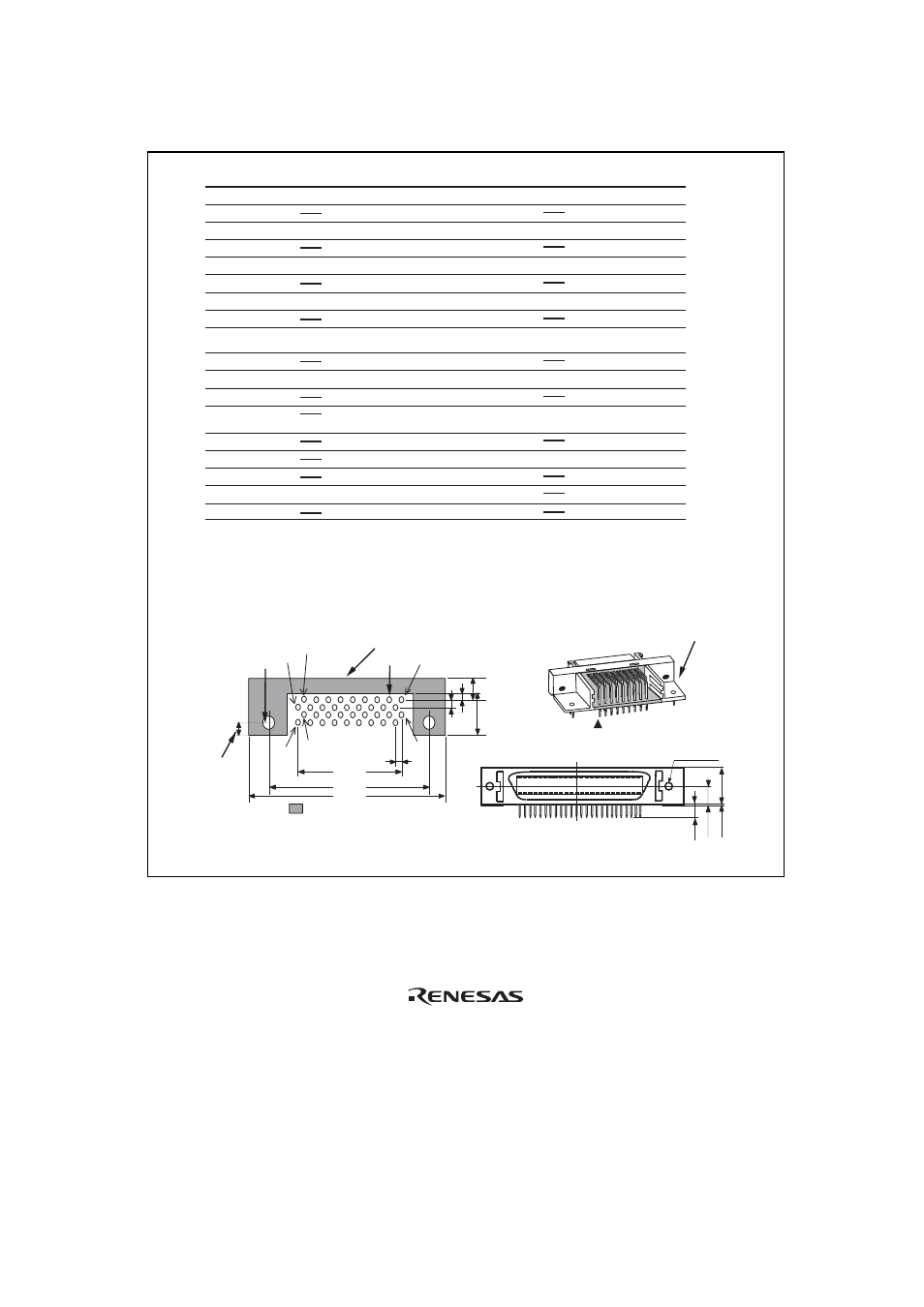
H-UDI port connector
(Pin 1 mark)
(top view)
Unit: mm
4.8
M2.6 x 0.45
9.0
0.3
3.9
H-UDI port connector (front view)
3. The emulator monitors the GND signal of the user system and detects whether or
not the user system is connected.
4. When the user system interface cable is connected to this pin and the MPMD pin is
set to 0, do not connect to GND but to the MPMD pin directly.
5. Connect /RESETP and /RESETA to the user system if required, as shown in figure 1.5.
Pin
No.
Signal
Input/
Output
Note
/AUDSYNC
N.C.
N.C.
TCK
GND
AUDATA0
GND
AUDATA1
GND
GND
GND
GND
GND
GND
GND
AUDATA2
AUDATA3
UVCC
TMS
/RESETP
/RESETA
GND
GND
/TRST
(GND)
TDI
GND
GND
GND
GND
GND
GND
GND
TDO
/ASEBRK /
BRKACK
Input
Input
User reset
Input
Input
Output
Input/
output
Output
Output
Output
Output
Output
Output
Output
Output
Output
Output
1
2
3
4
5
6
7
8
9
10
11
12
13
14
15
16
17
18
19
20
21
22
23
24
25
26
27
28
29
30
31
32
33
34
35
36
Pin
No.
Signal
Input/
Output
SH7362
Pin No.
Note
*1
*1
*2
*2
*2
*5
*2
*3
AUDCK
N.C.
: Pattern inhibited area
Edge of the board
(connected to the connector)
0.7
+0.1
0
2
1.27
1
3
4.5
1.1
1.905
9.0
21.59
37.61
43.51
36
35
4
2.8
+0.1
0
φ
4.09
H-UDI port connector (top view)
*4
SH7362
Pin No.
L14
L15
M13
M14
M16
J17
M15
L13
K14
K15
N13
D15
D12
K13
φ
Figure 1.2 Pin Assignments of the H-UDI Port Connector (36 Pins)