Renesas Emulator System SH7362 User Manual
Page 14
6
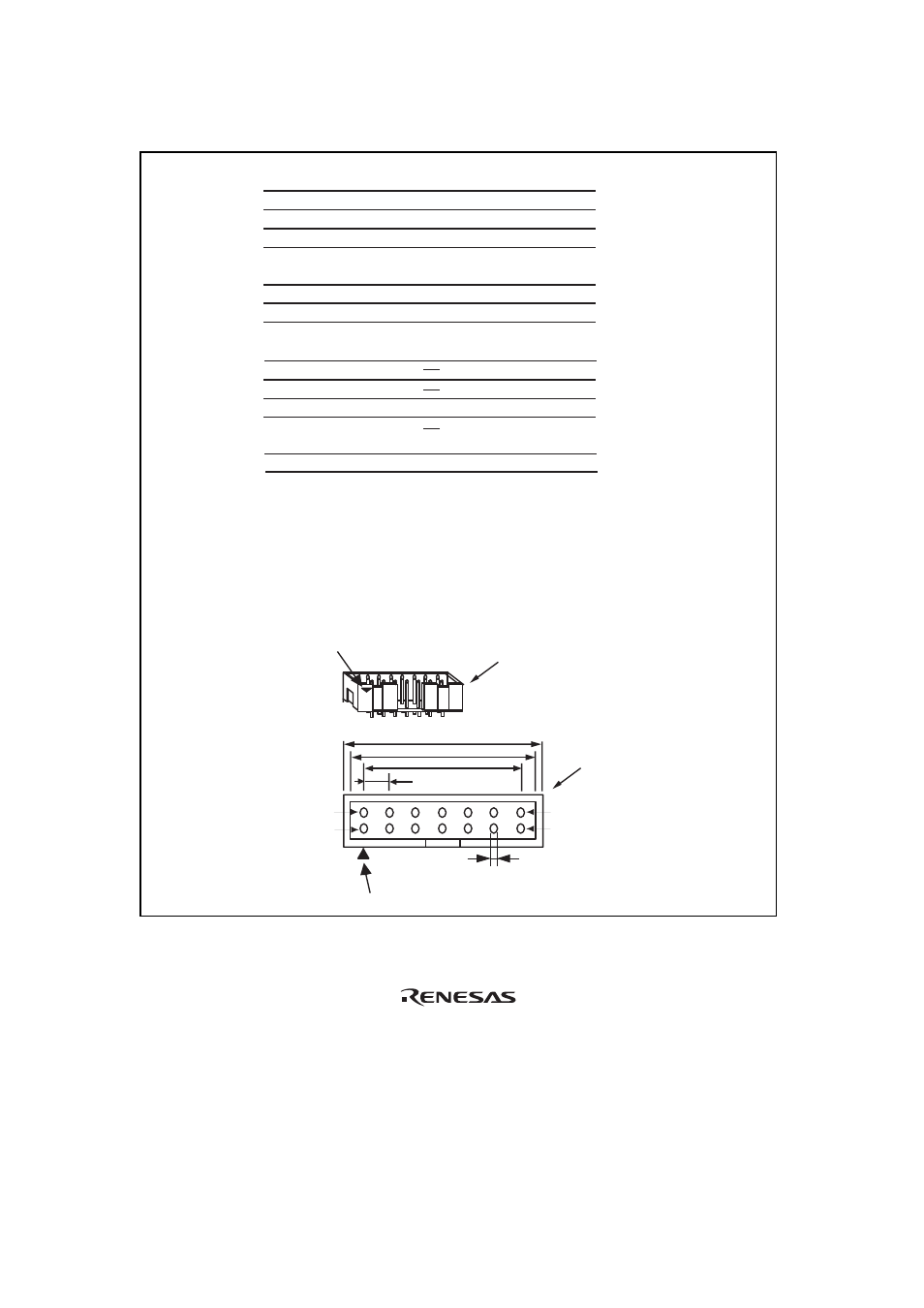
Pin 1 mark
Notes: 1. Input to or output from the user system.
2. The symbol (/) means that the signal is active-low.
3. The emulator monitors the GND signal of the user
system and detects whether or not the user system
is connected.
25.0
23.0
6 x 2.54 = 15.24
(2.54)
0.45
Pin 1
Pin 8
Pin 7
Pin 14
Pin 1 mark
H-UDI port connector (top view)
H-UDI port connector
(top view)
Pin No.
Signal
1
2
3
4
5
6
7
8
9
11
10, 12,
and 13
14
TCK
/TRST
TDO
/ASEBRK
/BRKACK
TMS
TDI
/RESETP
/RESETA
N.C.
(GND)
UVCC
GND
Input/
Output*
1
*2
*2
GND
*3
Output
Input
Input
Output
Input/
output
Input
Input
Output
Output
Output
4.
When the user system interface cable is connected to
this pin and the MPMD pin is set to 0, do not connect to
GND but to the MPMD pin directly.
5.
Connect /RESETP and /RESETA to the user system
if required, as shown in figure 1.6.
Note
User reset
*2
*5
*4
SH7362
Pin No.
J17
L13
K15
N13
K13
K14
D15
D12
Unit: mm
Figure 1.3 Pin Assignments of the H-UDI Port Connector (14 Pins)
- Single-Chip Microcomputer M34551T2-MCU (42 pages)
- M3T-FLX-80NRA (6 pages)
- 70 (162 pages)
- M16C/30P (102 pages)
- PROM Programming Adapter PCA7427G02 (20 pages)
- R0E572110CFK00 (40 pages)
- H8/325 Series (20 pages)
- Single-Chip Microcomputer H8/36079 (27 pages)
- Direct Dummy IC M3T-DIRECT100S (4 pages)
- M3A-2152 (95 pages)
- PCA7755D (6 pages)
- M16C/6N5 (106 pages)
- SH7085 (50 pages)
- QFP-144 (23 pages)
- H8/3834 Series (22 pages)
- RSKM16C62P (3 pages)
- H8/33937 (22 pages)
- Single-Chip Microcomputer H8SX/1622 (5 pages)
- E6000 (29 pages)
- PCA7400 (18 pages)
- PCA4738FF-64 (20 pages)
- SuperH HS7339KCU01HE (43 pages)
- M16C FAMILY (103 pages)
- PCA7412F-100 (20 pages)
- 4513 (210 pages)
- M34551E8FP (16 pages)
- Dummy IC M3T-SSOP36B-450 (4 pages)
- Emulation Pod M30100T3-RPD-E (52 pages)
- Converter Board for M30102 M30102T-PTC (4 pages)
- SH7145 (31 pages)
- HS1653ECN61H (36 pages)
- Converter Board R0E521276CFG00 (4 pages)
- PCA7302E1F-80 (18 pages)
- H8/3814 Series (21 pages)
- H8S/2646 Series (20 pages)
- SuperHTM Family SH7125 Series (40 pages)
- M30262T-PTC (4 pages)
- SH7670 (82 pages)
- H8/3864 Series (20 pages)
- Emulator System M3T-MR100 (306 pages)
- 38K0 (6 pages)
- PLQP0176KB-A (40 pages)
- Direct Dummy IC M3T-DIRECT80S (6 pages)
- PCA4738L-80A (26 pages)
- Converter Board R0E5212BACFG00 (6 pages)