Assembly – RIDGID SP6263 User Manual
Page 16
16
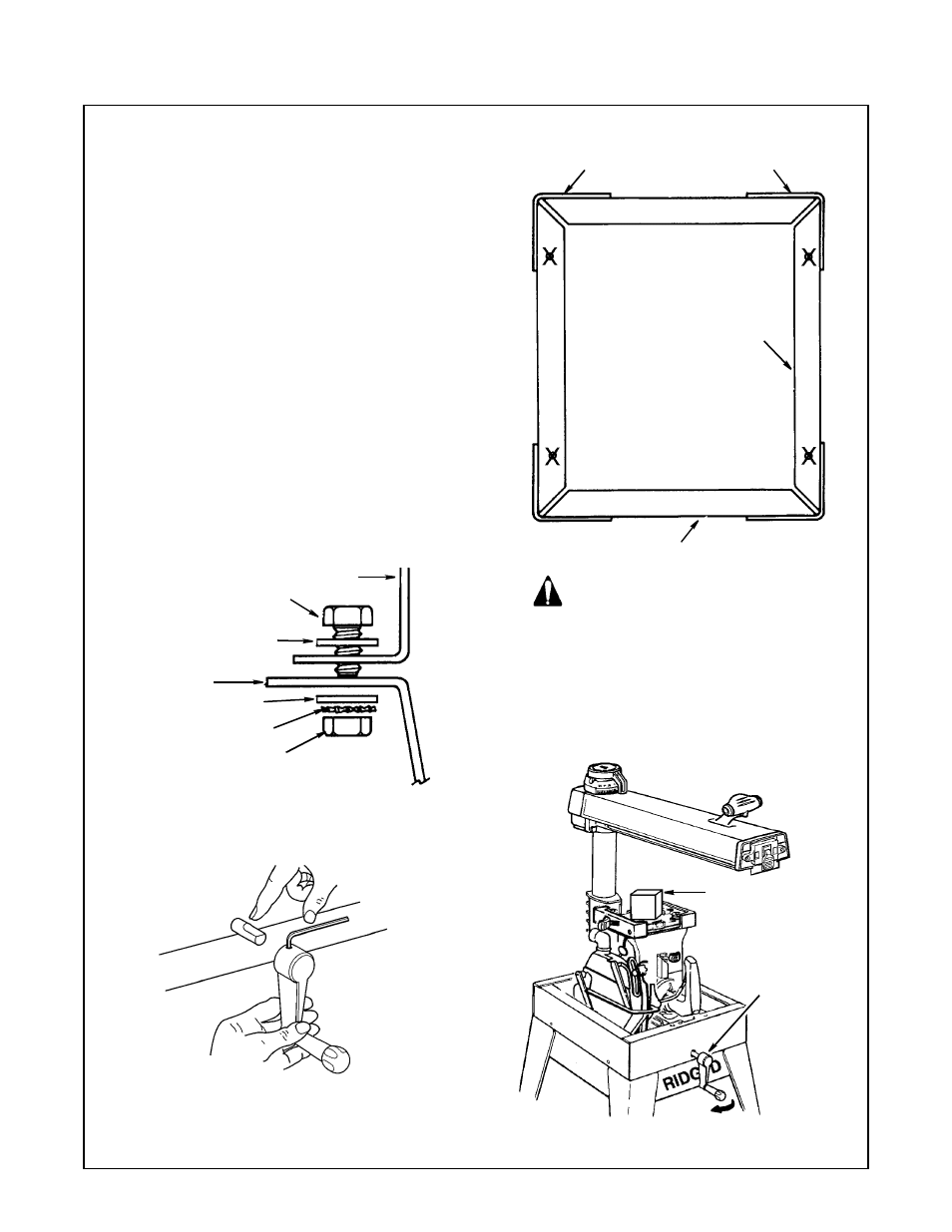
Mounting Saw
1. From among the loose parts, find the fol-
lowing hardware:
4 Hex Head Screws, 5/16-18 x 5/8
4 Lockwasher, 5/16 in. External Type
8 Washers, 11/32 ID
4 Hex Jam Nuts, 5/16-18
2. Place saw on legs so that holes in bottom
of saw line up with holes marked X in top of
legs and RIDGID logo on leg set is facing
front.
3. Install screws, washers and nuts as
shown.
4. If you mount the saw on any other
RIDGID base or flat bench, make sure Ele-
vation Crank has proper clearance to rotate.
The saw must be bolted down. Position saw
to slope slightly rearward, so when the car-
riage is installed it will not roll forward due to
gravity.
Attach Elevation Crank.
Install crank on elevation shaft. Be sure set-
screw is tightened on flat of shaft.
Elevate arm approximately 3 to 4 Inches.
Remove shipping block and discard.
WARNING
Saw must slant slightly towards rear to
keep blade carriage from rolling for-
ward. Workpiece or saw can move
unexpectedly if leg set rocks. Fingers,
hand or arm could be cut off by blade
contact. Adjust leveling feet before
using saw.
Saw Base
Hex Head
Screw
Flat Washer
Stiffener
Lockwasher
Hex Nut
Flat Washer
Leg
Leg
Side
Stiffener
Front Stiffener
(Turn clockwise
to raise arm)
Elevation Crank
Shipping Block
Assembly