Dds ports: rj45, Dds rx and tx led indications, 9 dds ports: rj45 – RuggedCom RUGGEDBACKBONE RX1510 User Manual
Page 32: 10 dds rx and tx led indications
Chapter 3
Installation
RuggedBackbone™ RX1510
Installation Guide
26
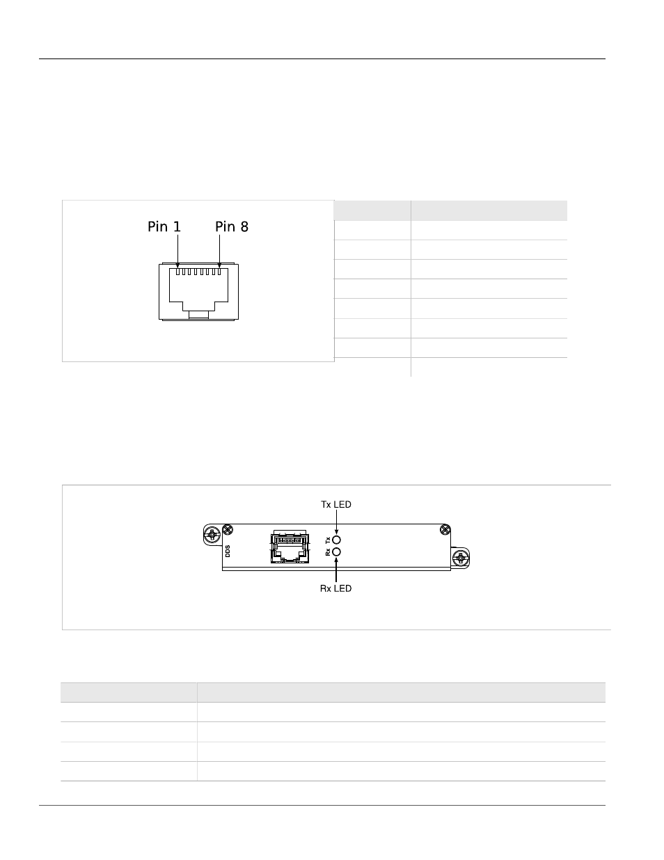
DDS Ports: RJ45
Section 3.9
DDS Ports: RJ45
The RX1510 supports DDS port line modules with RJ45 connections. The 56 kbps DDS port is compatible with
Bellcore standards. Each DDS module features a single 56/64 kbps DDS line interface with a standard RJ45
receptacle.
Figure 53: RJ45 DDS Pin Configuration
Table 9: RJ45 DDS Pin Assignment
RJ45 Pin
Description
1
R1: Transmit data to network (Ring 1)
2
T1: Transmit data to network (Tip 1)
3
NC
4
NC
5
NC
6
NC
7
T: Receive data from network (Tip)
8
R: Receive data from network (Ring)
Section 3.10
DDS Rx and Tx LED Indications
The DDS module features Rx and Tx LED indicators that display transmit and receive status.
Figure 54: DDS Module Rx and Tx LED Indicators
The following tables describe the DDS module Rx and Tx LED status indications:
Table 10: DDS Rx LED Indications
Rx LED Color
Status
GREEN
Frame sync detected and signal OK.
YELLOW
Signal OK, but no frame sync.
RED
Loss of signal.
OFF
The interface is not enabled.