Venting – Raypak 302B-902B User Manual
Page 25
25
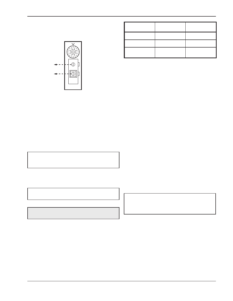
SINGLE
STAGE
TANKSTAT
STAGE 1
CONNECTION
ATTACH STAGE 1 CONNECTIONS
ON HEATER TO THE SINGLE STAGE
TANKSTAT AS SHOWN IN THE DIAGRAM ABOVE.
Fig. 23: Single-Stage Tankstat
Consult the wiring diagram shipped with the heater in
the instruction packet or at the end of this section. The
stage-selector terminals are for the remote tank con-
trol through the heater’s 24 VAC transformer. DO NOT
attach any voltage to the stage-selector terminals.
Before starting the heater, check to ensure proper volt-
age to the heater and pump.
Venting
General
Flue Exhaust Tee
An optional Flue Exhaust Tee is available to facilitate
horizontal venting. Any reference to horizontal venting
that exits the back of the heater requires this tee. Refer
to Table L for the appropriate kit for your model.
NOTE: If any of the original wire supplied with the
heater must be replaced, it must be replaced with
similar sized 105°C wire or its equivalent.
NOTE: For 87%-efficiency boilers, see special
instructions on page 39.
CAUTION: Proper installation of flue venting is criti-
cal for the safe and efficient operation of the heater.
Appliance Categories
Heaters are divided into four categories based on the
pressure produced in the exhaust and the likelihood of
condensate production in the vent.
Category I – A heater which operates with a non-pos-
itive vent static pressure and with a vent gas
temperature that avoids excessive condensate pro-
duction in the vent.
Category II – A heater which operates with a non-pos-
itive vent static pressure and with a vent gas
temperature that may cause excessive condensate
production in the vent.
Category III – A heater which operates with a positive
vent pressure and with a vent gas temperature that
avoids excessive condensate production in the vent.
Category IV – A heater which operates with a positive
vent pressure and with a vent gas temperature that
may cause excessive condensate production in the
vent.
See Table M for appliance category requirements.
Model
Diameter
Order Number
302B
5”
011838
402B-502B
6”
011839
652B, 752B,
902B
8”
011840
Table L: Flue Exhaust Tee Kits
NOTE: For additional information on appliance
categorization, see appropriate ANSI Z21 Standard
and the NFGC (U.S.), or B149 (Canada), or
applicable provisions of local building codes.